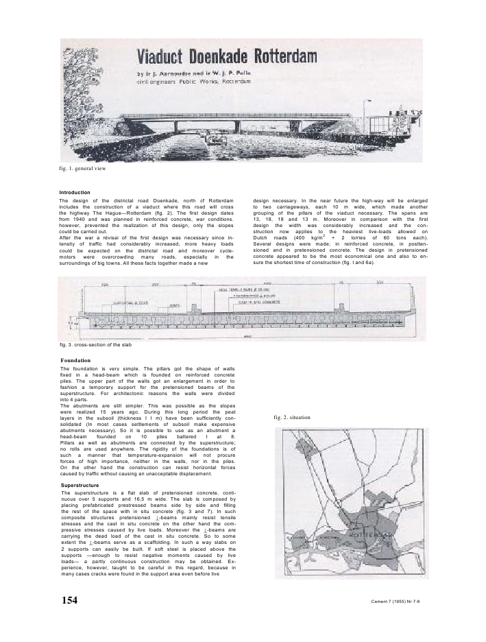
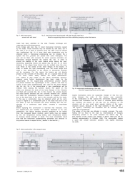
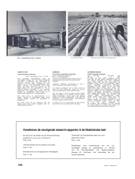
fig. 1. general viewIntroductionThe design of the districtal road Doenkade, north cf Rotterdamincludes the construction of a viaduct where this road will crossthe highway The Hague--Rotterdam (fig. 2). The first design datesfrom 1940 and was planned in reinforced concrete, war conditions.however, prevented the realization of this design, only the slopescould be carried out.After the war a r?visai of the first design was necessary since in-tensity of traffic had considerably increased, more heavy loadscould be expected on the districtal road and moreover cycle-motors were overcrowding many roads, especially in thesurroundings of big towns. All these facts together made a newdesign necessary. In the near future the high-way will be enlargedto two carriageways, each 10 m wide, which made anothergrouping of the pillars of the viaduct necessary. The spans are13, 18, 18 and 13 m. Moreover in comparison with the firstdesign the width was considerably increased and the con-struction now applies to the heaviest live-loads allowed onDutch roads (400 kg/m2+ 2 lorries of 60 tons each).Several designs were made; in reinforced concrete, in postten-sioned and in pretensioned concrete. The design in pretensionedconcrete appeared to be the most economical one and also to en-sure the shortest time of construction (fig. I and 6a).fig. 3. cross-section of the slabFoundationThe foundation is very simple. The pillars got the shape of wallsfixed in a head-beam which is founded on reinforced concretepiles. The upper part of the walls got an enlargement in order tofashion a temporary support for the pretensioned beams of thesuperstructure. For architectonic reasons the walls were dividedinto 4 parts.The abutments are still simpler. This was possible as the slopeswere realized 15 years ago. During this long period the peatlayers in the subsoil (thickness I I m) have been sufficiently con-solidated (In most cases settlements of subsoil make expensiveabutments necessary). So it is possible to use as an abutment ahead-beam founded on 10 piles battered I at 8.Pillars as well as abutments are connected by the superstructure;no rolls are used anywhere. The rigidity of the foundations is ofsuch a manner that temperature-expansion will not procureforces of high importance, neither in the walls, nor in the piles.On the other hand the construction can resist horizontal forcescaused by traffic without causing an unacceptable displacement.SuperstructureThe superstructure is a flat slab of pretensioned concrete, conti-nuous over 5 supports and 16,5 m wide. The slab is composed byplacing prefabricated prestressed beams side by side and fillingthe rest of the space with in situ concrete (fig. 3 and 7). In suchcomposite structures pretensioned -beams mainly resist tensilestresses and the cast in situ concrete on the other hand the com-pressive stresses caused by live loads. Moreover the -beams arecarrying the dead load of the cast in situ concrete. So to someextent the -beams serve as a scaffolding. In such a way slabs on2 supports can easily be built. If soft steel is placed above thesupports --enough to resist negative moments caused by liveloads-- a partly continuous construction may be obtained. Ex-perience, however, taught to be careful in this regard, because inmany cases cracks were found in the support area even before livefig. 2. situation154 Cement 7 (1955) Nr 7-8fig. 4. slab transversal fig. 5. slab transversal prestressed with high tensile steel barsarmed with soft steel Note the supporting blocks and the scaffolding hanging under the beams.loads had been admitted on the slab. Possibly shrinkage andcreep are due to this phenomenon.Every bridge slab also has to resist transversal moments causedby live loads. These moments may be resisted by soft steel, but inthis case a lot of steel is required since the steel must be placedvery uneffectively (fig. 4). A more ideal slab construction may beobtained when a transversal prestressing can be created. By asystem like this -beams are placed with some interspace. Thejoint will be filled with concrete for which purpose joint-laths aretemporarily hanged between the beams (fig. 5a). In order toensure the stability of the outer beams when raising the post-tensioning, supporting blocks are placed (fig. 5b and 9). At somedistance of the edges these blocks may be omitted since the pres-sure 'flows' to the centre of the lower flanges of the beams. Inorder to obtain the right prestressing over the entire length andwidth a free deformation of the beams In transversal directionwill be necessary. For this reason the beams are not directlyplaced on the concrete of the pillars, but on a special kind of velt,I cm thick, which easily follows the small deformations.This viaduct is also based on the above mentioned structure,however some further development has been made for thesupport-area. At the support-area pretensioned junction beamsare placed between the upperflanges of the -beams and fixed bymeans of the same posttensioning also used for the lower flanges(fig. 6a, 6b). So in the support-area a new upperflange will becreated. After placing the junction beams the space on thepillars and between the ends of the lower flanges of the X-beamsare filled with concrete (fig. 6c). In this manner the junction beamswill resist tensile stresses and the concrete between the -beamswill resist the compressive stresses caused by negative momentsdue to the dead load of the cast in situ concrete and the live loads.In this way a construction may be obtained which will be conti-nuous in regard to a considerable part of the dead load and to thelive loads. In fact this structure has some similarity with the con-struction of a continuous steel girder, crossing a cross-beam(fig. 6d).Before applying this construction a load-test was executed. Onlythe support-area was imitated. The results appeared to be verysatisfactory; the failure bending moment appeared te be higherthan the computed failure moment, which partly may be causedby the low temperature during testing (Low temperature seemsto increase tensile strength of steel). The most remarkable resultwas that the transverse posttensioning prevented any removal ofthe junction beams In respect to the -beams. In the test the -fig. 9. transversal prestressing of the slabNote the supporting blocks at the right.beams themselves were not supported; instead of this the con-crete between the ends of the beams was supported.In the construction of the viaduct the connection between super-structure and foundation will be found in concrete joints althoughthe X-beams are placed on velt (fig. 6c), its influence on thestructure will be very small when angular rotation of the super-structure occurs, because of the high elasticity of the velt (E100 kg/cm2). Practically the foundation will be centrally loadedunder any circumstances.The edges of the slab are effected in normal concrete. The scaf-folding will be fixed to the slab by intermedlance of hangerstemporarily placed in the joints between the beams (fig. 5b).The erection of the viaduct was started in March 1955 and will befinished approximately In October 1955. The construction makesa quick and simple execution possible, only slightly disturbingthe traffic.fig. 6. slab construction in the support-areaCement 7 (1955) Nt 7-8 155fig, 7. assembling of the -beams fig. 8. filling of joints Note the junction beams on the backgroundSAMENVATTINGViaduct Doenkade, Rotterdamdoor ir J. Aarnoudse en ir W. J. P. PelleDoor gewijzigde omstandigheden bleek hetvooroorlogse ontwerp voor het viaduct Doenkadeniet meer te handhaven. Een economische enpractische oplossing werd gevonden door toe-passing van in de fabriek voorgespannen beton-balken. Tezamen met opstortbeton vormen dezebalken een plaat, welke ten aanzien van heteigen gewicht van het opstortbeton en van demobiele belasting doorgaand is over meerderesteunpunten. Dit laatste wordt bereikt door toe-passing van koppelbalken, welke tussen de -balken worden geklemd d.m.v. dwarsnaspanning.Deze dient tevens om dwarsmomenten op tenemen, waartoe de onderflenzen dwars nage-spannen worden, voordat het opstortbeton isaangebracht.Het rijdek vormt met de onderbouw ??n stargeheel; geen rollen werden toegepast doch uit-sluitend betonscharnieren.SOMMAIREPont-viaduc de Doenkade ? Rotterdampar M. J. Aarnoudse, ing?nieur etM. W. J. P. Pelle, ing?nieurA cause de circonstances alt?r?es depuis la guerre,l'ancien projet du pont-viaduc ne s'est plus av?r?praticable.L'utilisation d'?l?ments pr?contraints en usine afourmi une solution ?conomique et pratique.Les poutres constituent avec le b?ton coul? surplace une dalle continue par rapport aux surchar-ges et au poids propre du b?ton coul? sur place.Ceci est obtenu ? l'aide de dalles ?clisses serr?esentre les poutres, en renvers?, par une pr?con-trainte transversale. D'autre part cette derni?res'oppose ? la flexion transversale: ? cet effet, lesmembrures sont pr?contraintes transversalementavant le coulage du b?ton sur place.Le tablier est fi? ? l'infrastructure par des articula-tions en b?ton; on ne s'est pas servi de rouleaux.ZUSAMMENFASSUNGViadukt Doenkade, Rotterdamvon Dipl.-lng. J. Aarnoudse undDipl.-lng. W. J. P. PelleEs zeigte sich, dass zufolge ver?nderter Verh?lt-nisse das vor dem Kriege entworfene Projekt f?rden Viadukt Doenkade nicht mehr beibehaltenwerden konnte. Man fand eine ?konomische undpraktische L?sung durch die Verwendung fabriks-m?ssig hergestellter vorgespannter Betontr?ger.Zusammen mit dem dar?ber an Ort und Stelleangebrachten Beton formen diese Tr?ger einePlatte, die bez?glich des Eigengewichtes des letzt-genannten Betons und der Verkehrslast eine ?bermehrere St?tzpunkte durchlaufende Konstruktionbildet. Dieser Zustand wird durch die Anordnungvon Koppeltr?gern erreicht, die zwischen denTr?gern mittels Quer-Nachspannung festge-klemmt werden. Diese dient zugleich dazu, Mo-mento in der Querrichtung aufzunehmen, zuwelchem Zwecke die unteren Flanschen in Quer-richtung nachgespannt werden, bevor der Betonan Ort und Stelle eingebracht ist.Die Fahrbahn formt zusammen mit dem Unterbauein starres Ganzes; es werden keine Rollen, son-dern ausschliesslich Betonscharniere verwendet.Versehenen de navolgende research-rapporten in de Nederlandse taal:De slip bij en de sterkte van de eindverankerings-systemen Freyssinet en Magnel.Prijs: f2,50.Literatuurstudie over de opbouw van beton.Prijs: f 1,50.Brandproeven op voorgespannen betonliggers.Prijs: f 1,50.Onderzoek van hoogwaardig staal voor voor-gespannen beton.Prijs: f 3,50.Bestellingen door overschrijving van het ver-schuldigde bedrag op postrekening nr. 351239van de Penningmeester der Betonvereniging,Zeeweg 24, Overveen, met vermelding der ge-wenste rapporten.156 Cemenl 7 (1955) Nt 7-8
Reacties