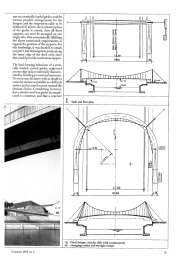
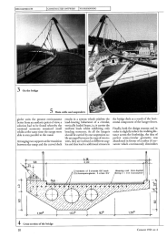
IBRUGGENBOUW ICONSTRUCTIEFONTWERP IVOORSPANNING IFOOTBRIDGE IN KELHEIM,GERMANYProf.Dr.-lng. J?rg Schlaich and Dr.-Ing. J?rgen Seidel, Schlaich, Bergermann und Partner, ConsultantsConstruction Engineers, Stuttgart, FRGNear the town ofKelheim., theRiver Altm.?.hl is being rem.odelled as part oftheMain-Donau Canal. The new waterway drives a 47-m.etre wide concrete corridorbetween the historical old town and its suburbs. The rom.antic, attractive m.eadowlandscape will disappear, to be replaced by a com.pletely new townscape. Hoping tosom.ewhat relieve the pain ofthis transition with an attractive footbridge,Rhein-Main-Donau AG, the owners ofthe canal and its infra-structure,announced alim.ited com.petition to provide a bridge over thecanal which harm.onized with thenew townscape both in its construction, and in the design ofits bridgeheads.The task was made particularlydifficult by the fact that theclearance required not only afree spanof61,84 m to accomodate canaland service paths, but also aheight of7,6m above the mean water level, and 3 mabove the points to be connected. Allo-wing for a maximum gradient of 10%,this would necessitate ramps 30 m long.For this reason, cooperation betweenengineers and architects was necessaryas early as the competition stage. Out ofsix planning groups invited to compete,the first prize was won by thejoint pro-ject submitted by the Munich architectsAckermann and Partners and the Stutt-gart engineers Schlaich Bergerman andPartners. They were then awarded thecontract to design and detail the foot-bridge.DesignTwo considerations were ofcrucial im-portance for the designers.Firstly, the reaction to the technical so-briety of the irreversible waterway hadto be a technically neat and at the sametime light solution; not one that tried topander to the romantic townscape.Second, theramps should be arranged ina straight line along the banks ofthe ca-nal instead ofas spiral and step construc-tions, as these would block the view forany pedestrians coming out ofthe townwhowanted to cross or merely teach thecanal and, in particular, would ruinwhat was now an attractive area in frontofthe old town gate-tower. The fitst de-sign sketch therefore included twostraight ramps integrated into the floodprotection walls ofthe canal, and a sus-8pension bridge crossing the canal at aright angle (fig. 1).A suspended footpathwas the obvious choice, in that it is notonly light in appeatance, but also requi-res thesmallest possible constructionheight, and thusdoes not make theramps anylonger thanabsolutelyneces-sary. Furthermore, a suspension bridgeis more natural and aesthetically plea-sing than a somewhat sterile cable-stay-ed bridge.However, neither pedestrians no physi-cal forces are particularly fond of cor-ners, so we had the idea ofmerging theramps and bridge deck in an uninterup-ted link - a solution which would makethe walking distance across the foot-bridge only slightly longer. The pointthatdecided us, and made the design fi-nal was that the continuous, curvedform ofthe deck could be used for stati-cal purposes, in that the structural de-mands of the slab could be satisfied bysuspending the concrete deck along onesingle side only. All that was needed wasfor two anchored towers to be inclinedover the bridge, and for a suspension ca-bIe to be suspended from them. Becausethey were anchored along the inner ra-dius ofthe deck slab, the angle ofinclineof the hangers would be constantlychanging; the pedestrians crossing thebridge would therefore experience theimpression of the three-dimensionalstructure (photo 4).Load~bearing behaviourThe fact that at least three vertical sup-ports, not arranged in a straight line, arenecessary to provide external equilibri-Cement 1991 nr. 6I1 II I1- - . ~/I 00II cC8~1 I~:I II Ii:J:JI cc ,CCI00 ,I00I Ij.f:.f:ccW-11 I:::E:::EI.,~ 00Irl1.,.1 6181., 1.,.18um ona vertically loaded girder, enablesvarious possible arrangements for thehangers and the suspension cable to bededuced. If, ashere, the horizontal planeof the girder is curved, then all threesupports can even be arranged on onesingle side, thus automatically fulfillingthe above~mentioned requirements asregards the position ofthe supports. Forthis foothridge, it was decided to attachnotjust 3, but 38 hangers to points alongthe inner edge of the deck only, sincethis would provide continuous support.The load-bearing behaviour ofa verti-cally loaded, curved girder, supportedon one edge only, is essentially characte-rized by bending an torsional moments.To overcome the latter with as slender aconcrete section as possible is a difficuitmatter, and so asteel section seemed theobvious choice. Considering, however,that aslendersteel box girder is compli-cated to construct, and that a concrete1 Task and Hrst planColumnSl?!zeOlQ.Q.EECCCl::ITl'-M"x~r . =16.89Final design: circular slab with continuouslychanging radius and straight rampsI' , .1.00 I~ ---=6-f'-=--84 -~~~ ---.r----~--l ~-~~- -l.... ~~~Cement 1991 nr. 6 9IBRUGGENBOUW ICONSTRUCTIEFONTWERP IVOORSPANNING5 Main cable andsuspendersgirder suits the present environmentbetter from an aesthetic point ofview, asolution had to be found whereby thetorsional moments remained smallwhilst at the same time the ramps wereable to run parallel to the canal.Arranging two supportsat the transitionbetween the ramp and the curved deckresults in a system which exhibits theload-bearing behaviour of a circuiar,vertically loaded beam, i.e. it carries theuniform loads whilst exhibiting onlybending moments. As all the hangersshould be carried by one suspension ca-bIearranged between the tops oftwo to-wers, they are inclined at different ang-les and thus lead to additional stresses inthe bridge deck as a result of the hori-zontal component ofthe hanger forces.Finally, both for design reasons and inorder toslightly reduce thewalking dis-tance across the footbridge, the idea ofperfect semi-circular geometry wasabandoned in favour ofa radius ofcur-vature which continuously diminishesl, 1833022 lendons ol 5 slronds 0.6" eoch Wearing cool: 6cm Aspholl22 lil zenspannglieder. 5 Lilzen 06" /Belog: 2 x ]r.m Gussospholtow 0w4 Cross-section ofthe bridge10 Cement 1991 nr. 6from R = 37,79 mat the centre of thebridge to R = 18,89 m at the point oftransition to the ramp (fig. 2). Mathema-tically, the ground plan ofthe deck slabis described by and involution of thecircle and its projection bya parabola.this onlyslightly alters the load-bearingbehaviour described above.DetailingAcross the entire length of the bridge,the prestressed deck, ofB45 concrete, isasymmetricin section, as is illustrated infigure 4. The sections at the ramps haveno weight-reducing hollow parts. Thisbridge section provides the bendingstrength around the horizontal axis ne-cessary for ring beam behaviour, whilstat the same tirne weighing as little aspossible, and allowing sufficient spacefor accornmodating the tendons. It isasymmetrie in order to keep the appliedmoments srnall, and to facilitate faste-ning ofthehangers. In the curved part ofthe bridge, the tendons are arrangedwith constant vertical eccentricity,whilst for the ramps, a parabolic shapehas been chosen. The bridge deck isfIXed monolithically,both to the slender1030 x 400 mm2colums provided at thetwo curvelramp transitions and to theabutments. This eliminates the need forthe provision offurther bearings.The cable structure consists of38 han-gers, 2,3 mapart, the suspension cablerouted between the two towers and an-chored in the abutments, the backstaycables ofthe steel towers and the neces-sarymountings and fittings (photo 5). Allcables are locked, protected against in-ternal corrosion and coated several ti-mes to protect them externally. Thehangers, with a wire tensile strength of1570 N/mm2, are 30 mm in diameter.The suspension cable is 90 mm in dia-meter, and the towerbackstaycables 117mmo The minimum breaking strenghtsofthe three cable types are ca1culated at860, 7900 and 13 360 kN respectively;values which have been confirmed bytests.The mountings and fittings - forkedcable sockets, double-sleeved cableclamps, supports and saddles - at thetops of the towers, are made of GS25CrMo4- or GS26 CrM04 cold-tempe-red, cast steel. The tubular tower, madeof St 52 steel, is 600 mm in diameter,with a wall thickness of 100 mrn. Theover-weighty dirnensions ofthe towerheadsand, above all, ofthe backstay ca-bles, which unfortunately impair theappearance of lightness originally in-tended for the bridge, result from thelack ofspace at the anchoringpoints andCement 1991 nr. 6the formal condition that the towers beno higher than the gate-tower ofthe oldtown.In service state, the tower carries 15 000kN via a spherical bearing to the foun-dation structure,which also receives thetensile load of the two backstay cables,amounting to 12 500 kN. The founda-tion structure consists of two concreteblocks approximately 5x 6 x 2m3in size,connected to each other via a compres-sion member. As aresuit, the horizontalcomponenrs of the tower and backstaycable forces cancel each other out, lea-ving mainly vertical forces to be trans-mitted to the foundation rock.At the to-wer, the applied forces are transmitteddirectly into the dolomite, while at theanchoring cable foundation block theyare transmitted indirectly into the rockvia 20 perrnanent anchors, 36 mm indiameter, and made of St 1080/1230steel.To assessthe oscillationbehaviour ofthebridge, the lowest natural frequencies ofthe stiffening girder and of the indivi-dual cables were determined. UsingRayleigh's method, the following valueswere calculated:fl (symmetric) = 0,69 Hz,f2 (syrnmetric) = 1,11 Hz andfl (antimetric) = 0,6 Hz.With the variation of the drag factor,which had been determined by windtunnel testing, and given the lowest na-tural frequency, the criticalwind veloci-ty (galopping) was calculated at 55 mis.This is therefore higher than the localwind velocity to be expected. Althoughvortex excitations can be anticipated,contingent upon Strouhal figures ofbe-tween 0,138 and 0,169 atawind velocityofbetween 4 and 5 mis (again, these fi-gures were determined in a wind tun-nel), the concomitant dynamie pressureof0,016 kN/m2is so lowthatthere is nodanger ofunstable oscillation.Unpleasant oscillations mayalso be sa-fely excluded under normal pedestrianuse, with an anticipated disturbing fre-quency of 1,5 Hz to 3 Hz.Construction and erectionFollowing completion of the substruc-ture (abutments, anchoring and towerfoundations), the deck was constructedfrom falsework. The procondition forthe construction ofa self-anchored sus-pension bridge was satisfied by the factthat the canal was only to be completedafter thebridge had beenbuilt.The con-Crete for the deck slab was placed in asingle pouring, startingfrom both abut-ments simultaneously. Subsequently,.the towers, which were delivered exworks complete with saddle and an-chors, were erected to a height approxi-mately 150 mm lower than their finalposition, and mounted with the help oftheir anchoring cables and two auxiliarycables each. The hanger clamps couldnow be mounted on the ready-madesuspension cabie, which had been laidout across the deck, at appropiatelymarked points, and the hangers werefastened to these clamps. Mobile craneswere used to lift the suspension cablein-to its saddles. In single steps that hadbeen determined mathematically priorto construction, the towers were raisedby applying jacks to the base; internaltendons were progressivelystressed, andthe falsework gradually lowered. Thus,the bridge were gradually stressed andstripped ofits falsework.Since correction of the geometry andforces on the bridge could only be car-ried out by the application ofpressure tothe base ofthe towers, utmost precisionwas vital in the ca1culation and cuttingoflengths to size, both at prefabrieationstage and in the field, particularly at theinterfaces between concrete and cablestructures. To this end, the cables notonly had to be cut to size in a prestressedstate, but a tolerance of10 mm had to beachieved in respect ofthe three-dimen-sionalcoordinates for the anchoring no-des. ?wing to the increased effortsofallthose involved in executing the project,itproved possible to fulm these strictconditions. The construction work wasaccompanied by detailed geodesie mea-surements of the tower tops, the mid-point of thesuspension cable and theanchoring points. As the measured geo-metry concurred to within tolerabie li-mits with the desired geornetry, forcemeasurements were only carried out onthe prestressing elements, on the be-drock anchors of the backstay founda-tions and on the towerjacks.11

Reacties