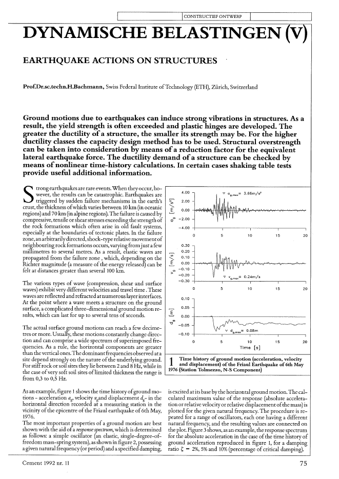
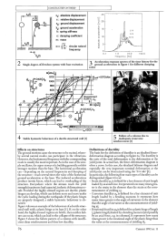
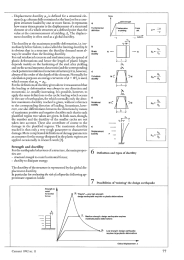
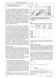
I ICONSTRUCTIEFONTWERP IDYNAMISCHE BELASTINGEN VEARTHQUAKE ACTIONS ON STRUCTURESProf.Dr.sc.techn.H.Bachtnann, Swiss Federal Institute ofTechnology (ETH), Z?rich, SwitzerlandGround tnotions due to earthquakes can induce strong vibrations in structures. As aresult, the yield strength is often exceeded .and plastic hinges are developed. Thegreater the ductility ofa structure, the stnaUer its strength may beo For the higherductility classes the capacity design tnethod has to be used. Structural overstrengthcan be taken into consideration by means ofa reduction factor for the equivalentlateral earthquake force. The ductility demand ofa structure can be checked bytneans ofnonlinear titne-history calculations. In certain cases shaking table testsprovide useful additional information.4.00 3.66m/s'N 2.00V>"'-E 0.00~0> -2.000-4.000 5 10 15 200.300.20V>0.10"'-E 0.00~0>-0.10>- -0.20-0.300 5 10 15 200.100.05E'---' 0.000>"1J-0.05v d = O.OBm-0.10Q.max0 5 10 15 20Time [sJ1 Thne history ofground tnotion (acceleration, velocityand displacetnent) ofthe Friaul Earthquake of6th May1976 (Station Toltnezzo, N-S Cotnponent)The various rypes of wave (compression, shearand surfacewaves) exhibit very different velocities and travel time. Thesewavesare reflected and refracted atnumerous layerinterfaces.At the point where a wave meets a structure on the groundsurface, a complicated three-dimensional ground motion re-suIts, which can last for up toseveral tens ofseconds.The actual surface ground motions can reach a few decime-tres or more. Usually, these motions constantly change direc-tion and can comprise a wide spectrum ofsuperimposed fre-quencies. As a mIe, the horizontal components are greaterthan thevertical ones.The dominantfrequencies 0 bservedatasite depend strongly on the nature ofthe underlying ground.For stiffrock or soi! sites they lie between 2 and 8 Hz, while inthe case ofvery soft soil sites oflimited thickness the range isfrom 0,3 to 0,5 Hz.Strong earthquakes are rare events. when they occur, ho-? wever, the results can be catastrophic. Earthquakes are. triggered by sudden failure mechanisms in the earth'scrust, the thickness ofwhichvaries between 10 km (in oceanicregions)and 70 km(in alpineregions). The failure is caused bycompressive, tensile orshearstressesexceeding the strengthofthe rock formations which often arise in old fault systems,especially at the boundaries of tectonic plates. In the failurezone, anarbitrarilydirected, shock-type relative movementofneighbouring rock formations occurs, varying fromjust a fewmillimetres to severalmetres. As aresuit, elastic waves arepropagated from the failure zone, which, depending on theRichter magnitude (a measure ofthe energy released) can befelt at distances greater than several100 km.As an example, figure 1shows the time history ofground mo-tiOllS - acceleration ag, velociry vgand displacement dg- in thehorizontal direction recorded at a measuring station in theviciniry ofthe epicentre ofthe Friaul earthquake of6th May,1976.The most important properties ofa ground motion are bestshown with the aid ofa response spectrum, which is determinedas follows: a simple oscillator (an elastic, single-degree-of-freedom mass-spring system), as shown in figure 2, possessingagiven natural frequency (or period) and aspecified damping,is excited atits base by the horizontal ground motion. The cal~culated maximum value ofthe respollse (absolute accelera-tion or relative velociry or relative displacementofthe mass) isplotted for the given natural frequency. The procedure is re-peated for a range ofoscillators, each one having a differentnatural frequency, and theresulting values are connected ontheplot. Figure 3shows, as an example, the response spectrumfor the absolute acceleration in the case ofthe time history ofground acceleration reproduced in figure 1, for adampingratio ~ = 2%, 5% and 10% (percentage ofcritical damping).Cement 1992 nr. 11 75__________~I-C-O-N-S-TR--U-C-T-IE_F-O_NTWE~._._--RP---'------ _Xa: absolute displaeernentx: relative displacementxg: ground displacementxg: groundaccelerationk: spring stiffnesse: damping eoefficientm: mass0)= H,: eireular naturalfrequency25c.~o 15'-'"'"ug 10'":;2 5.D-?2 %LO 10.0Frequency [Hz]100.02 Singie-degree-of-freedom. system. with base excitation 3Acceleration response spectra ofthe tim.e history for theground acceleration in figure 1 for different dam.pingratios-80-6~?.I-. ~'63~"? H Et>M HM[kNm]12001000 ~=;~~~~~==~=--800 ~--+--HHfrr",e....+-'~-+~H-+600~~'f-H::.M-4 Stabie hysteretic behaviour ofa ductile structural wall (1]Effects on structnresThe ground motions cause the structure to be excited, where-by several natural modes can participate in the vibrations.However, the fundamental frequencywith the correspondingmode is usually the most important. As in the case ofthesim-ple oscillator, the upper storeys ofa buildinggenerallyexhibitstronger motions than the base. The horizonral accelerationcan - depending on the natUl-al frequencies and damping ofthe structure - reach several times the value ofthe horizontalground acceleration at the base. The induced accelerationsproduce inertia forces, which can lead to overloading of thestructure. Everywhere where the stresses reach the yieldstrength (maximumload capacity),inelasticdeformationsre-sult. Provided the highly stressed regions are ductile, plastichinges can develop, which can deform more and more underthe cyclic loading during the earthquake. Ifthe plastic hingesare properly designed, a stabIe hysteretic behaviour is ob-tained.Figure 4 shows an example ofthe behaviour ofa ductile struc-tural wall with a plastic hinge at its base [1]. IE, on the otherhand, the highly stressed regions are brittIe, then sudden fail-ure can occur, which can lead to the collapse ofthe strucrure.Figure 5 shows the failure pattern ofa column with insuffi-cient shear reinforcement and thus low ductility.765 Failure ofa coIum.n due toinadequate transversereinforcement (I]Definitions ofductilityThe basis for the definition ofductility is an idealised force-deformation diagram according to figure 6a. The ductility isthe ratio of the total deformation to the deformation at theyield point. In actual fact, the force-deformation diagram isoften a curve. In this case, the idealized bilinear diagram andespecially the very important nominal deformation at theyield point can be determined using the '3/4 rule' [1].In particular, the following four main types ofductilitycan bedistinguished (figure 6 bfo e}.- Strain ductility fteis defined for a barelement ofunit lengthloaded byan axial force. Ir represenrs how many times grea-ter is the strain in the element than the strain at the com-mencement ofyielding ?y;- Curvature ductility ft~ is defined for a bar element ofunitlength loaded by a bending moment. Ir represents howmany times greater is the angle ofcurvature in the elementthan theangle ofcurvature at the commencement ofyield-ing . = f.10?For thedefinitions ofductilitygivenabove itwas assumed thatthe loading or deformation was always in one direction andmonotonic, i.e. steadily increasing. It is possible, however, toapply the same definitions to the cyclic loading which occursin the case ofearthquakes, for which normally only the abso-lute maxitnum ductility reached is given, without referenceto the corresponding direction ofloading. Sometimes, how-ever, one also differentiates between the directions by meansofmaximum positive and negative ductility such that in eachplastified region two values are given. In both cases, though,the number and the ductility of the smaller cyclesare nottaken into account. These also contribute of course to thedamage in the plastified regions. The maximum ductilityreached is thus onlya very rough parameter to characterizedamage. More complicated definitions ofdamage parametersas a measure for the energydissipated in the plastic regionsareapplied occasionally in research work [3].SL "Elastic"= very highstrength:\ design earthquake requires no plaslic deformalions\\\SLr----.. Medium sIrenglh: design earthquake requiresmoderate plastic deformationsSlrenglh 10resislhorizontalforces~,r---------~'--...-..::--...'e_..2P: Lowslrenglh: design earthquakerequires large plastic deformationsGlobal displacemenl 8Cement 1992 nr. 11 77100 [Hz]10 20 33pseudo-acceleration (absolute)Fmax= k .xmaxFmax = ! .x = 0)2. x where 0) = jf!max?? max' .m m m~ ah0.129 90.60.10 0.50.08 0.40.06 0.30.04 0.20.02 0.10.00 0.00.2 0.5 0.5 2 3The maximum stressing ofthe spring or ofthe structure canthus be determined from the statie action ofan'inertia force' = mass x pseudo-acceleration = 'equivalentearthquake force'Equivalent force methodIn the case ofa large number ofstructures for buildings ?t isadvantageous to carry out the earthquake design with the aidofthe equivalentforee method.With this method the earthquakeaction is represented by an equivalent horizontal force. Thusna dynamic, but solely astatic analysis, has to be carried out.'elastic'behaviour 1 - 1.5 1 - 1.3'natural'ductility 2.5 2 1.2'limited'ductility 3.5 3'full' ductility 6 5strength than in the case oflowerductility, but also that due tothe capacity design, a high degree of earthquake safety isachieved.Ta determine the equivalent horizontal earthquake force thewhole structure is replaced by a simple oscillator (single de-gree offreedomsystem), the frequency ofwhichis equal to thefundamental frequency ofthe structure. For its mass the totalvibrating mass ofthe structure is used. In the case ofthe elasticsystem shown in figure 2, the maximum force in the springFmax'which corresponds to the maximum stresses ?nthe struc~ture, occurs at the moment of maximum relative displace-ment Xmax:Tabel!Standard va1ues [or the design displacement ductility factorsframe systems structural structuralof reinforced walls of wals ofductility class dconcrete or reinforce masonrysteel conctete (unreinforced)For the design and detailing, the fo11owing hold:- fot structures in the ductility class 'elastic' behaviour and'natural' ductility, a conventional design such as that for thestressingdue to gravityandwindloadingmaybe carriedout.In the case of'natural' ductility, however, same special de-sign rules have to be observed (e.g. for the stirrup and con-finement reinforcement in reinforced concrete columns);- for structuresin the ductility classes 'limited' and 'full' duc-tility, a eapacitydesign (see below) has to be carried out, whichis specifically directed towards earthquake actions. In thiscase, a larger number ofspecial design rules have to be ob-served.The ductility classes 'limited' and'[u11' ductility not onIy havethe advantage that one has to provide for a smaller structuralDuctility classesIn the choice ofa design ductility for practical purposes a re-striction to simply a few ductility classes is appropriate. Thispermits areasonable stepwise systematisationof the designand detailing. Furthermore, in the construction of at leastsame of the storeys, certain structural elemenrs are identicalthus furthering rationalisation. For example, for reinforcedconcrete structures the formwork is the same and the rein-forcement is prefabricated in the farm ofcages.In table 1 typical displacement ductility factors ftLJ for fourdifferentductility classes and for three types ofstructural sys-tem to resist horizontal farces are summarized.The first solution is an extreme solution and usually ratheruneconomical, since majorexpenditure is necessary forachieving the required strength. Because strong earthquakesoccur onIy very seldom, damage caused by plastic deforma~tion ofthe structure could be quite acceptable provided therewas na risk of collapse. The second possibility offers a goodeconomic solution, particularly in areas ofvery high seismicactivity, as long as relatively major damage to structural andnon-structural elements due to the associated large structuraldeformations, is acceptable. In addition, the high ductilityde-mand must be covered by an appropriate design and acorres-ponding detailing. In areas ofmoderate seismic activity or inthe case ofstructures with onIy moderate levels ofacceptabledamage, an intermediate solution is aften preferred.In addition it must be pointed out that the structures of thethree solutions of figure 7 have different effective dynamicstiffness and sa different natural frequencies. This in itselfmay produce a favourable or an unfavourable effect depen-ding on the shape ofthe relevant response spectrum (fig. 8).For a design earthquake of a certain intensity therefore astructure can be designed in very different ways. Figure 7shows three possibilities.Onepossiblesolutionis to design thestructure to have a very high strength. In this way the designearthquake can be resisted elastically, i.e. without plastic de~formations, and there is no ductility demand.A second possible solutionis to design the structurewith.alowstrength but a high ductility, whereby the effect ofthe designearthquake is to produce large plastic defonnations and thus (dd d bI d b h h k f 1 8Elastic design spectra for stiffground continuousin a ition consi era e amage, ut wit out t e ris 0 co - lines) and Il1ediuIl1~stiffground (broken lines) andlapse. In this case, there is a high ductility demand. But inter- 5% daIl1pingmediate solutions can also be chosen, by designing with a L.,.-._ _- - ~~---~_~---~-,-Jmedium strength and accepting moderate plastic deforma-tions for the design earthquake, whereby the ductility de-mand remains relatively low._ _ _ _ _ _ _ _ _ _ _ 1CONSTRUCTIEF ONTWERP78 Cement 1992 nr. 11n~ = (Ftot -F~) .Fn Frin mnI-j -Fj ,Ijmj~hn2 hj m2t1 ml//' -- r, /''"a) b) c)9 Building with floor masses and distribution oftheequivalent earthquake forceThe pseudo-accelerationis the spectraIaccelerationfiom adesignresponsespectrumatthe samefrequency as the fundamental fre-quency ofthe structure.Figure 8 shows as an example the de-sign response spectra (valid for a simple oscillator) for the dif-ferent earthquake zones in Switzerland [4].In the section 'Strength and ductility' it was shown that toavoid collapse the structural strength required to resist hori-zontal forces decreases with increasing ductility. The magni~tude ofthe structural strength is determined by the size oftheequivalent force. The greater the equivalent force the higherthe required structural strength. Therefore, for the purpose ofsttuctural design, the equivalent force which applies for anelastic system('elastic equivalent force') can be reducedaccor-ding to the chosen design ductility /lA' This is achieved by di-viding the elastic equivalent force by a so-called behaviourfactor q:1F=-FelqFor this purpose the following assumptions are usual [1]:q = /lA (principle of equal displacement), orq = .J 2/lA- 1 (principle ofequal energy)In general, the second principle should be chosen, as the fintone is only appropriate for frequencies ofless than about 0.7Hz.In the design ofastructurefor any kind ofaction, such as grav-ity, wind, earthquake, etc., the structural strength is evaluatedusing strengthvalues smaller than the average expected values(e.g. bya factor of1.25);in addition, the structural strengthcal-culated on this basis is further reduced by a resistance coeffi-cient (e.g. 1.2). These two factors lead to a considerable excessof strength, the so-called overstrength. In earthquake design,however, it is fully justified for the actual average structuralresistance to be onlyjusthigher than the equivalentforce defi-ned above. Ir is practical, therefore, to reduce this equivalentforce by a factor Co to take into account the overstrength (e.g.Co = 11(1.25' 1.2) == 0.65).This leads to the following relationship for the equivalentfor-ce:F - C . ad .. Mtot - 0 totqFtot total equivalent horizontal earthquake force;ael spectral acceleration from the design response spectrumfor a simple elastic oscillator;q behaviour factor;Cement 1992 nr. 11Co factor ro take account ofoverstrength;Mtot totalvibrating mass ofstructure.In the above relationship all essential influence factors can beconsidered: ael Can be specified as a function of frequency,damping, ground (soillr?ck) type, seisrnic zone, importanceof the structure, probability of occurrence of design earth-quake, ete. In some codes and standards only a basic value forael (design response spectrum) is given and the other above-mentioned influences are accounted for by rneans ofmulti-plicative factors.The totalequivalentearthquake force has to be distributedover the height ofthe structure and is divided into forces perstorey, whichactat the heightofthefloor level. Ingenera!, thisdivision is based on a distribution, which in the case ofa con-stant masslheight relationship is triangnlar. However, to takeinto account the stresses due to shear forces resulting from theexcitation of the higher vibration modes of the structure, afraction of the equivalent force (e.g. 10%) acting as a singleforce at the top ofthe structure is considered. The distributionofthe equivalent force shown in figure 9 Can be representedmathematically as follows:mj' hjFe.ot total equivalent horizontal earthquake force (base shear);11 equivalent force per storey;P n single force acting at top ofstructure;m- floor mass;h/ height measured from the level ofembedment.Using the equivalent forces acting at the floor levels, the sec-tional forces (bending moments, shear forces, axial forces) canbe deterrnined for the earthquake load case. If the centre ofrnass and the shear centre do not coincide within a storey, tor-sional stresses arise. Special rules are required to deterrninethese stresses [1].Capacity designOue to earthquake action, cyclic plastic deformations occur.This is generally not the Case with gravity and wind action,where primarily elastic deformations occur. As a consequen-ce, the sectional forces due to earthquake action can only bedetermined by conventional design methods ifsmall plasticdeformations are expected ('elastic' behaviour and 'natural'ducility, tabie 1).A relativelylarge equivalentforce is required,which often leads to a high structural strength for horizontalforces and thus to an uneconomic structure. Nevertheless, theconventional design involves significant uncertainties, espe-cially with regard to ductility and the actual danger ofbrittlefailure. Usually, the capacity design method is much more eco-nomic and much safer. Itcanhe characterized as follows [1,5]:'In astructure, theplastified regions are deliberately chosen, and cor-respondingly designed anddetaiIed, so that theyarestifficientIyducti-Ie. The other regions aregiven a higherstructural strength (capacity)than theplastifiedones, in orderthattheyalwaysremainelastic. In thisway it isguaranteed that the chosen mechanisms, even in the case oflarge structural diformations, always remain functionalJor energydissipation'.The capacity design method, which was developed mainly inNew Zealand, therefore guarantees a certain chosen and spe-cified ductility and provides a high degree ofseismic safety. Iris based on the following principles:79ICONSTRUCTIEFONTWERPStress limitationILayout of the structureThe maximum possible stresses induced in the structure arekept within acceptable limits over the whole range ofdefor-Choice of design ductilitymation by means ofcorresponding measures. II Determination of theSpecifying the regions ofenergy dissipation equ?valent earthquake forceThe regions ofenergy dissipation in the structure are specifi-Ically determined and designed and detailed according to theirstressing. Elastic analysis to determine the sectional farcesIdue to the equivalent earthquake force and gravity loadingProtection ofthe other regionsfrom overstressingRegions which tend to fail in a brittle manner or whichin ge-Small ductility Full and limited ductilityneral are not suitable for stabie energy dissipation, are protec-ted from excessivestressingand always remain elastic, no mat- ConventionalCapacity designter what the intensity ofthe earthquake. designDuctile structural behaviourThe complete structure exhibits ductile behaviour with a Conventional Redistribution of the sectional forceslarge deformation capacity, despite brittle parts.design of Design of potentiallyThese four principles ellable a deterministic designprocedure the wholeplastic regionsand the restrietion of special constructional measures to a Determination ofoverstrengthlimited number ofwell-defined regions. structure in the plastic regionsSince, uader earthquake action, the stressing ofthe individualConventional design ofstructural elements is difficult to estimate and above all de-pends on the deformation ofthe structure, the structural ele-the elastic regionsments essential to maintainthe integrityofthe structure haveConventional Detailingto be designed for the effective forces emanating from theplastified regions. That means thatthese elements musthave a detailing of Plastic Elasticgreaterstrengththanthat ofthe specified plastified regions. In the whole regions: regions:this way, the design is made independentofthe deformations.structurespecial ConventionalIfthe deformations ofthe structure are greater than expected, rules rulesthen no new plastic hinges are developed, but those regions ofthe structure that are alreadyplastifiedwill deforrn somewhatmore. lEthe plastified regions are designed correctly, the pre-10 Scheme for design proceduresence ofasufficientlylarge ductility, in excess ofthat assumedfor calculating the equivalentearthquakeforce, is guaranteed.The plastic regions (plastic hinges) thereby limit the stressingofthe structure. Ir is thusguaranteed that the remaining elas-tic or more or less brittlestructural elements are not over-stressed.Figure 10 shows schematicallythe different stages ofthe de-sign process for reinforced concrete structures underearthquake action. One possibility is to design for small ('na~11 Vertical plan ofsix storey reinforced concrete frametural') ductility following conventional design and detailingprocedures.Especiallyfor mediumor high earthquake action,25.80capacity design offers considerable advantages. In contrast tot 9.60 6.60 9.60fotherdesign methods, it necessitates detailingwhich takes ac-r rcount of ductility dernand only in clearly defined potential .--' f.-plastic regions. The other regions ofthe structure, which re- 0
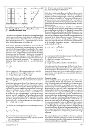
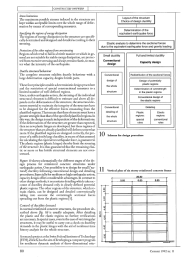
Reacties