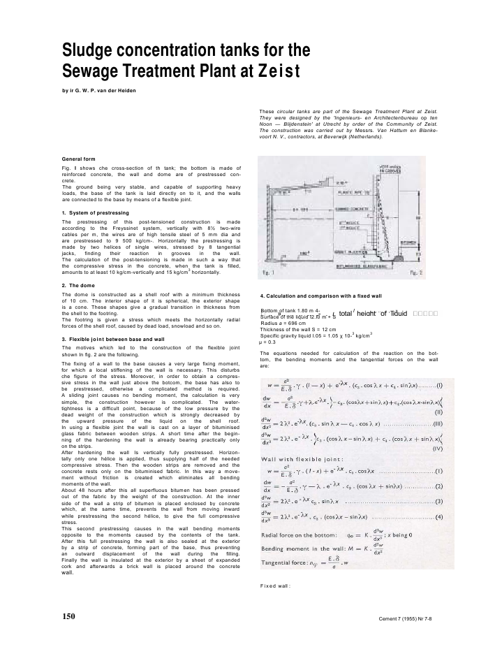
Sludge concentration tanks for theSewage Treatment Plant at Zeistby ir G. W. P. van der HeidenThese circular tanks are part of the Sewage Treatment Plant at Zeist.They were designed by the 'Ingenieurs- en Architectenbureau op tenNoon -- Blijdenstein' at Utrecht by order of the Community of Zeist.The construction was carried out by Messrs. Van Hattum en Blanke-voort N. V., contractors, at Beverwijk (Netherlands).General formFig. I shows che cross-section of th tank; the bottom is made ofreinforced concrete, the wall and dome are of prestressed con-crete.The ground being very stable, and capable of supporting heavyloads, the base of the tank is laid directly on to it, and the wallsare connected to the base by means of a flexible joint.1. System of prestressingThe prestressing of this post-tensioned construction is madeaccording to the Freyssinet system, vertically with 8? two-wirecables per m, the wires are of high tensile steel of 5 mm dia andare prestressed to 9 500 kg/cm-. Horizontally the prestressing ismade by two helices of single wires, stressed by 8 tangentialjacks, finding their reaction in grooves in the wall.The calculation of the post-tensioning is made in such a way thatthe compressive stress in the concrete, when the tank is filled,amounts to at least 10 kg/cm-vertically and 15 kg/cm3horizontally.2. The domeThe dome is constructed as a shell roof with a minimum thicknessof 10 cm. The interior shape of it is spherical, the exterior shapeis a cone. These shapes give a gradual transition in thickness fromthe shell to the footring.The footring is given a stress which meets the horizontally radialforces of the shell roof, caused by dead load, snowload and so on.3. Flexible joint between base and wallThe motives which led to the construction of the flexible jointshown In fig. 2 are the following.The fixing of a wall to the base causes a very large fixing moment,for which a local stiffening of the wall is necessary. This disturbsche figure of the stress. Moreover, in order to obtain a compres-sive stress in the wall just above the botcom, the base has also tobe prestressed, otherwise a complicated method is required.A sliding joint causes no bending moment, the calculation is verysimple, the construction however is complicated. The water-tightness is a difficult point, because of the low pressure by thedead weight of the construction which is strongly decreased bythe upward pressure of the liquid on the shell roof.In using a flexible joint the wall is cast on a layer of bituminisedglass fabric between wooden strips. A short time after the begin-ning of the hardening the wall is already bearing practically onlyon the strips.After hardening the wall Is vertically fully prestressed. Horizon-tally only one h?lice is applied, thus supplying half of the neededcompressive stress. Then the wooden strips are removed and theconcrete rests only on the bituminised fabric. In this way a move-ment without friction is created which eliminates all bendingmoments of the wall.About 48 hours after this all superfluous bitumen has been pressedout of the fabric by the weight of the construction. At the innerside of the wall a strip of bitumen is placed enclosed by concretewhich, at the same time, prevents the wall from moving inwardwhile prestressing the second h?lice, to give the full compressivestress.This second prestressing causes in the wall bending momentsopposite to the moments caused by the contents of the tank.After this full prestressing the wall is also sealed at the exteriorby a strip of concrete, forming part of the base, thus preventingan outward displacement of the wall during the filling.Finally the wall is insulated at the exterior by a sheet of expandedcork and afterwards a brick wall is placed around the concretewall.4. Calculation and comparison with a fixed wallBottom of tank 1.80 m 4- I ,,., ... ,. ,--.?, ?.. ,. ., ,, .- , total height of liquidSurface of the liquid I2.I0 m + SRadius a = 696 cmThickness of the wall S = 12 cmSpecific gravity liquid I.05 = 1.05 10-3kg/cm3 = 0.3The equations needed for calculation of the reaction on the bot-tom, the bending moments and the tangential forces on the wallare:Fixed wall :150 Cement 7 (1955) Nr 7-8The integration constant c3 is immediately extracted fromequation I, by supposing x = 0, namely:All necessary values will then follow immediately from theequations I, 3 and 4:The liquid filling gives thus the next result:nqx = 0.731 (1-x) - 753.1 e- .cosx kg/cm1....................................... (I a) = - 2734.5 e- .slnXx kgcm/cm1.....................................................(3 a)qo = - 38.47 kg/cm' .........................................................................(4 a)The moment curve ( ----------------- ) is projected in fig. 3, the n,. curve(--------------) ?n fig. 4.In fig. 3 also the moment curve in the case of a fixed wall ( .......................)is projected, neglecting the small influence of the bending of thebottom.The maximum tangential stress in the wall laying at 142.4 cmdwabove the bottom ( dx= 0 in equation 2) the reinforcement iskept constant from this point to the bottom. From 142.4 cm +bottom to the top of the wall the reinforcement decreases linearly.The prestressing at this point amounts to:(1030-- 142.4) ? 1.05 ? I0-:|? 696 + 15 ? 12 = 828.66 kg/cm1,828.66equalling a radial force of = 1.19 kg/cm1. The prestressing696force at the top is: 12 ? 15 = 180 kg/cm'.This prestressing force(ny) by the first h?lice is produced in fig. 4 (------------------------- ), the pre-stressing force by the second h?lice is calculated by supposing thewall being externally loaded by a radial force to an amount ofI 19--- = 0.595 kg/cm2.Hence:6962?"?.= + r-^rr^;----------- ? x ??595= 0.100 (equation l,w = 0)3240.000 12 v M'The equations I, 3 and 4 are in this case:~ = - 414.12 4- 413.79 " . CosXx kg/cm1......................................... (lb)Mx = 1504.8. sin kgcm/cm1.............................................................. (3b)q0 = 21.13 kg/cm' ................................................................................ (4 b)The largest radial stress in the base thus amounts to 38.47-21.13 == 17.34 kg/cm1= 1.15 kg/cm2, the base being 15 cm thick.The curve representing the bending moments caused by thisprestressing (-------------- ) is projected in fig. 3; then,, -curve (...................)in fig. 4; the total tangential force is indicated by the curve --.--.The hatched difference between both moment curves representsthe bending moment to be met by the vertical reinforcement,while the difference between the two ,,-curves (also hatched)represents the resulting tangential force of the filled tank; thisforce diminishes from 414 kg/cm1near the bottom to normally180 kg/cm1at about 150 cm above it.The required vertical reinforcement follows from the bendingmoment with tank filled, the vertical pressure of the dead load ofthe construction reduced by the upward pressure from the liquidin the dome, and finally by the necessary minimum stress of10 kg/cm2in the concrete with the tank filled.The vertical pressure with the tank filled amounts to 32,8 kg/cm1.Without prestressing the vertical stress in the concrete wall, is:The reinforcement found by this calculation requires 8.5 two wirecables 5 mm dia vertically, and horizontally two helices of singlewires each increasing from 8 wires per m1at the top to 26 wiresper m1at 1.40 above the bottom (thus in total 16 wires to 52 wiresper m'). From the bottom to 140 cm height the reinforcementremains constant at 52 wires per m1.Sommaire page 153 Zusammenfassung Seite 153 Samenvatting blz. 153photo 5. lower part of the wall with vertical wires and plastic tubes seenfrom the inner side of the wall before placing the inner scaffoldingphoto 6. exterior of the tankwall with the vertical two wire cables afterremoving the scaffolding151

Reacties