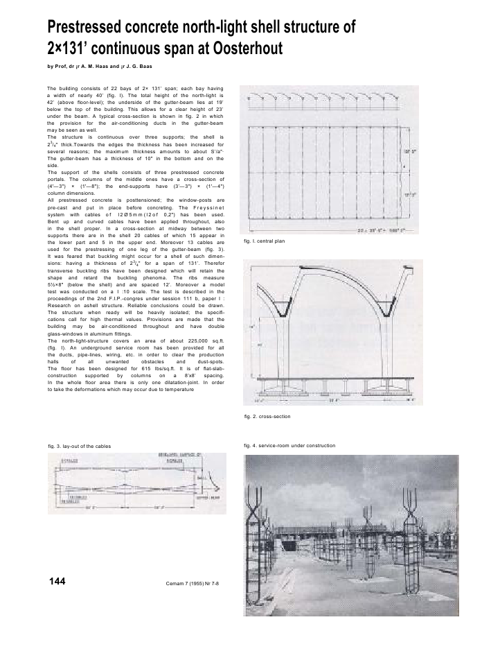
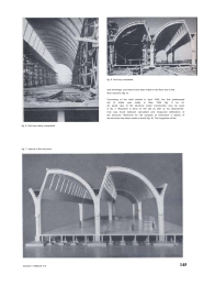
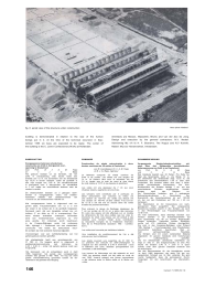
Prestressed concrete north-light shell structure of2?131' continuous span at Oosterhoutby Prof, dr ?r A. M. Haas and ?r J. G. BaasThe building consists of 22 bays of 2? 131' span; each bay havinga width of nearly 40' (fig. I). The total height of the north-light is42' (above floor-level); the underside of the gutter-beam lies at 19'below the top of the building. This allows for a clear height of 23'under the beam. A typical cross-section is shown in fig. 2 in whichthe provision for the air-conditioning ducts in the gutter-beammay be seen as well.The structure is continuous over three supports; the shell is23/4" thick.Towards the edges the thickness has been increased forseveral reasons; the maximum thickness amounts to about S'/a"?The gutter-beam has a thickness of 10" in the bottom and on theside.The support of the shells consists of three prestressed concreteportals. The columns of the middle ones have a cross-section of(4'--3") ? (1'--8"); the end-supports have (3'--3") ? (1'--4")column dimensions.All prestressed concrete is posttensioned; the window-posts arepre-cast and put in place before concreting. The Freyssinetsystem with cables o f l 2 ? 5 m m ( l 2 o f 0,2") has been used.Bent up and curved cables have been applied throughout, alsoin the shell proper. In a cross-section at midway between twosupports there are in the shell 20 cables of which 15 appear inthe lower part and 5 in the upper end. Moreover 13 cables areused for the prestressing of one leg of the gutter-beam (fig. 3).It was feared that buckling might occur for a shell of such dimen-sions: having a thickness of 23/4" for a span of 131'. Therefortransverse buckling ribs have been designed which will retain theshape and retard the buckling phenoma. The ribs measure5??8" (below the shell) and are spaced 12'. Moreover a modeltest was conducted on a I :10 scale. The test is described in theproceedings of the 2nd F.I.P.-congres under session 111 b, paper I :Research on ashell structure. Reliable conclusions could be drawn.The structure when ready will be heavily isolated; the specifi-cations call for high thermal values. Provisions are made that thebuilding may be air-conditioned throughout and have doubleglass-windows in aluminum fittings.The north-light-structure covers an area of about 225,000 sq.ft.(fig. I). An underground service room has been provided for allthe ducts, pipe-lines, wiring, etc. in order to clear the productionhalls of all unwanted obstacles and dust-spots.The floor has been designed for 615 Ibs/sq.ft. It is of flat-slab-construction supported by columns on a 8'x8' spacing.In the whole floor area there is only one dilatation-joint. In orderto take the deformations which may occur due to temperaturefig. I. central planfig. 2. cross-sectionfig. 3. lay-out of the cables fig. 4. service-room under construction144 Cemam 7 (1955) Nr 7-8flg. 6. first bay completedand shrinkage, provisions have been made in the floor and in thefloor-columns (fig. 4).Concreting of the shell started in April 1955; the first prestressedset of shells was ready in May 1955 (fig. 5 en 6).An aerial view of the structure under construction may be seenin fig. 7. Research is done on the site as well; so far closecomfor-mity was found between calculated and measured deflections ofthe structure. Moreover for the purpose of instruction a replica ofthe structure has been made of wood (fig. 8). The hugeness of thefig, 5. first bay nearly completedfig. 7. replica of the structureCement 7 (1955) Nr 7-8 145fig. 8. aerial view of the structure under construction Aero-photo Hotlandbuilding is demonstrated in relation to the size of the humanbeings put in it. At the time of the technical excursion in Sep-tember 1955 six bays are expected to be ready. The owner ofthe building is the C. Jamin Confectionery Works at Rotterdam.Architects are Messrs. Masselink, Bruins and van der Zoo de Jong.Design and execution by the general contractors: N.V. Nederl.Aanneming Mij v/h fa H. F. Boersma, The Hague and N.V Koninkl.Nederl. Mij voor Havenwerken, Amsterdam.SAMENVATTINGVoorgespannen betonnen shedschaal-constructie van 2?40 m doorgaande over-spanning te Oosterhoutdoor Prof. dr ir A. M. Haasen ir J. C. BaasHet gebouw bestaat uit 22 travee?n, elk van2x40 m overspanning; elke travee heeft eenbreedte van 12 m. De bovenkant van de shedschaalligt 12,75 m boven vloerpeil; onder de gootbalk iseen vrije hoogte van 7,00 m. De schaalconstructieis doorgaand over 3 steunpunten; de schaaldikteis 7 cm. welke om verschillende redenen naar deranden is verdikt.De dwarsschotten bestaan uit 3 gebogen raam-werken in voorgespannen beton. De midden-kolommen hebben een dwarsdoorsnede van130x50 cm; de eindkolommen 100x40 cm.Alle voorgespannen beton is uitgevoerd met na-gerekt staal; Freyssinet-kabels van 12 ? 5 mmzijn zowel in de schaal als in de gootbalk toegepast.Gevreesd werd, dat een dergelijke schaal zou uit-knikken (7 cm dikte op 40 m overspanning). Der-halve werden knikribben ontworpen. Bovendienwerd een modelonderzoek uitgevoerd op 1/10ware grootte. Dit onderzoek wordt beschrevenin de Congres-Bijdragen onder het onderwerp1Mb-, bijdrage I : Onderzoek van een shedschaal-consiructie'. Het leidde toe betrouwbare resul-De schalen zijn met isolerend materiaal afgedekt.Voorzieningen voor een luchtbehandeling van hetgehele gebouw werden getroffen.Het shedgedeelte heeft een grondoppervlak van21 000 m'. De begane grond is uitgevoerd inpaddestoelvloerconstructie met kolommen op2,40 ? 2,40 m ; onder het gehele gebouw loopt eenkruipruimte.Het betonwerk van de schaaldaken werd in April1955 begonnen: het eerste stel voorgespannenschalen was gereed in Mei 1955. Tot nog toe werdgoede overeenstemming gevonden tussen de be-rekende en de gemeten doorbuiging.SOMMAIREConstruction de sheds pr?contraints ? deuxtrav?es continues de 40 m?tres ? Oosterhoutpor M. le professeur Dr. Ir. A. M. Haaset M. J. G, Baas. ing?nieurLe b?timent comporte 22 sheds continus de2?40 m de port?e. Les sheds ont une largeur de12 m. La hauteur libre sous la retomb?e est de7.0 m, tandis que la cote du point le plus ?lev?du voile s'?l?ve a 12,75 m (au-dessus du plancher).Les voiles ont une ?paisseur de 7 cm qui, pourdiverses raisons, augmente vers les rives.Les tympans sont constitu?s par 3 portiques enb?ton pr?contraint. Les colonnes du milieu ontune section de 130?50 cm; celles aux abouts ontune section de 100?40 cm.Des c?bles Freyssi netde 12 ? 5 ont ?t? mis en oeuvre dans les voileset dans les poutres-caniveaux.Pour pr?venir le risque de flambage (?paisseur de7 cm sur port?e de 40 m) on a pr?vu des nervures.En outre des essais ont ?t? effectu?s sur un mod?lede dimensions dix fois plus petites que les vrais di-mensions du shed. Ces essais, qui ont conduit ? desr?sultats surs, forment l'objet d'une contributionau Deuxi?me Congr?s de la F?d?ration Internatio-nale de la Pr?contrainte (Question 1Mb - Contribu-tion I).Les voiles sont couverts par mat?riaux isolants.Une installation de conditionnement de l'air a ?t?pr?vue pour tout le b?timent.Les sheds couvrent une superficie de 21 000 m'.Le plancher est ex?cut? en dalle-champignon ets'appuie sur des colonnes ? 2,40 m d'entr'axe ; sousle b?timent une cave, destin?e principalement auxconduites, a ?t? am?nag?e,Les travaux do b?tonnage ont ?t? entam?s en avril1955; les premiers sheds ont ?t? pr?ts au mois demai 1955, Jusqu'? pr?sent une bonne concordancea ?t? obtenue entre la fl?che r?elle et la fl?che cal-cul?e.ZUSAMMENFASSUNGVorgespannte Shedschalenkonstruktion miteiner ?ber drei St?tzpunkte durchlaufendenUeberspannung von 2x40 m zu Oosterhoutvon Prof. Dr. Ir. A. M. Haasund Ir. J. G. BaasDas Geb?ude besteht aus 22 Hallen. Pro Halle be-tr?gt die Spannweite 2x40 m, die Breite 12 m.Die Oberkante der Shedschale liegt 12,75 m, dieUnterkante des Rinnenbalkens 7,00 m ?ber demFussboden. Die Schalen bilden eine ?ber 3 St?tz-punkte durchlaufende Konstruktion. Die Kon-struktionh?he der Schalen betr?gt 7 cm. mit ausverschiedenen Gr?nden angebrachten Verst?r-kungen nach den R?ndern zu.Die Querschotten bestehen aus 3 gebogenenRahmenkonstruktionen in Spannbeton. DerQuerschnitt der Zwischenstutzen ist auf 130?50cm, der von den Endst?tzen auf 100 cm ? 40 cmbemessen.Der Spannbeton ist mit Verwendung von nach-gezogenem Stahl ausgef?hrt. Die vorgespannteBewehrung besteht sowohl in den Schalen als auchin den Rinnentr?gern aus Freyssinet-Kabeln von12 ? 5 mm.Da man bef?rchtete, dass derartige Schalen aus-knicken k?nnten (7 cm Konstruktionsh?he aufeine Spannweite von 40 m) wurden Knickverstei-fungen entworfen. Uebcrdies wurden Modellver-suche auf I/10 nat?rlicher Gr?sse durchgef?hrt.Sie sind in den Kongress-Beitr?gen unter Entwurf1Mb, Beitrag I : Forschungsarbeit, eine Shedschalen-konstruktion betreffend, beschrieben. Man er-hielt vertrauensw?rdige Resultate.Die Schalen sind mit einem isolierenden Materialabgedeckt. Im ganzen Geb?ude sind Vorsehungenf?r Luftbehandlung getroffen.Die mit Shedschalen ?berdeckte Oberfl?che be-tr?gt 21 000 m'. Die Erdgeschossflur ist eine Pilz-decke mit St?tzen 2,40 m ? 2,40 m in Quer-schnitt; unter dem ganzen Geb?ude erstreckt sichein Kriechraum.Mit den Beconarbeiten f?r die Schald?cher wurdeim April 1955 begonnen; der erste Teil der vor-gespannten Schalen war im Mai vollendet. Bis jetztwurde festgestellt, dass die gemessenen Durch-biegungen mit den berechneten gut ?bereinstim-men.146 Cemem 7 (1955) Nr 7-8
Reacties