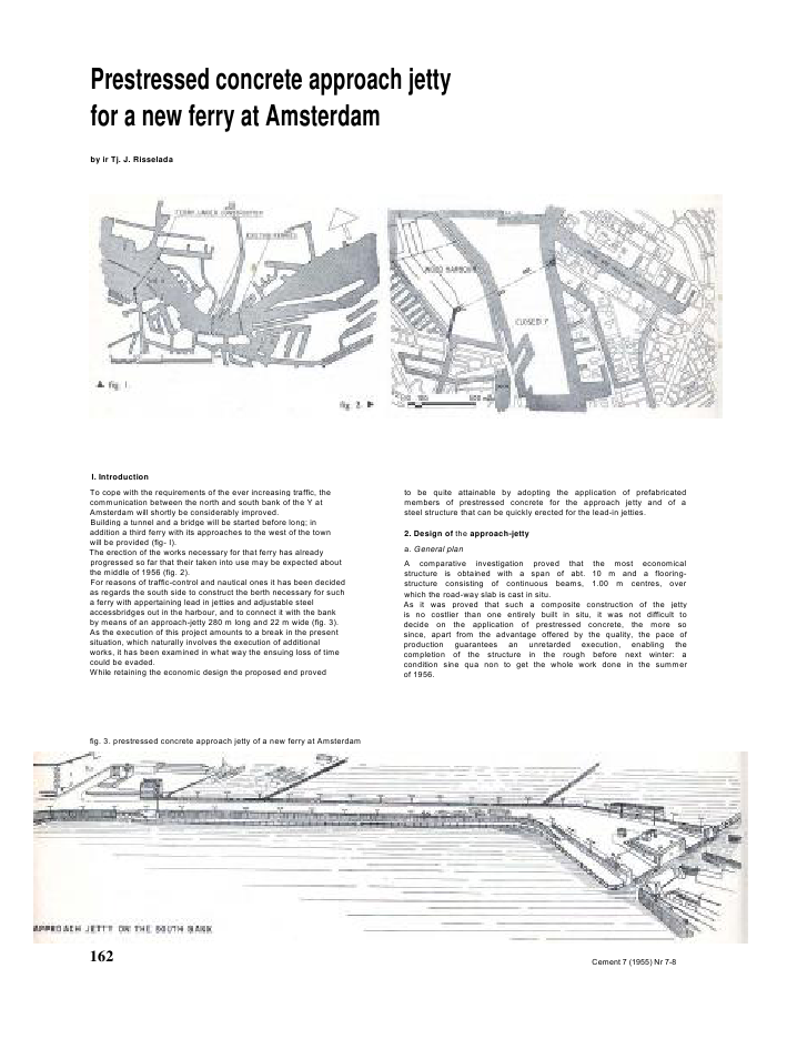
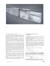
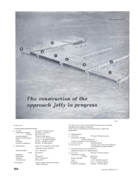
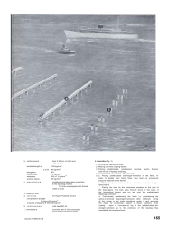
Prestressed concrete approach jettyfor a new ferry at Amsterdamby ir Tj. J. RisseladaI. IntroductionTo cope with the requirements of the ever increasing traffic, thecommunication between the north and south bank of the Y atAmsterdam will shortly be considerably improved.Building a tunnel and a bridge will be started before long; inaddition a third ferry with its approaches to the west of the townwill be provided (fig- I).The erection of the works necessary for that ferry has alreadyprogressed so far that their taken into use may be expected aboutthe middle of 1956 (fig. 2).For reasons of traffic-control and nautical ones it has been decidedas regards the south side to construct the berth necessary for sucha ferry with appertaining lead in jetties and adjustable steelaccessbridges out in the harbour, and to connect it with the bankby means of an approach-jetty 280 m long and 22 m wide (fig. 3).As the execution of this project amounts to a break in the presentsituation, which naturally involves the execution of additionalworks, it has been examined in what way the ensuing loss of timecould be evaded.While retaining the economic design the proposed end provedto be quite attainable by adopting the application of prefabricatedmembers of prestressed concrete for the approach jetty and of asteel structure that can be quickly erected for the lead-in jetties.2. Design of the approach-jettya. General planA comparative investigation proved that the most economicalstructure is obtained with a span of abt. 10 m and a flooring-structure consisting of continuous beams, 1.00 m centres, overwhich the road-way slab is cast in situ.As it was proved that such a composite construction of the jettyis no costlier than one entirely built in situ, it was not difficult todecide on the application of prestressed concrete, the more sosince, apart from the advantage offered by the quality, the pace ofproduction guarantees an unretarded execution, enabling thecompletion of the structure in the rough before next winter: acondition sine qua non to get the whole work done in the summerof 1956.fig. 3. prestressed concrete approach jetty of a new ferry at Amsterdam162 Cement 7 (1955) Nr 7-8fig. 5.b. Description of the project (fig. 4, see futheron)As a structural member of the approach-jetty a teebeam has beenchosen, 0.60 m high and 10.10 m long with a top flange 0.44 mwide, in which 34 wires of pretensioned high tensile steel 5 mmare embedded. Those beams are made In a factory speciallyequipped for the purpose.Each field is built up with 23 of those beams, I m centres, whichare provided with transverse diaphragms at two places in thefield; for them too prefabricated members are made use of.After the joints between the latter members and the webs of thegirders have been filled with mortar, those members are stressedby tensioning two bars ? 26 mm by means of the Dywidagprocess.To obtain continuity of the beams a longitudinal prestress isapplied over the capping beams. For that purpose the precastlongitudinal beams are provided with raised ends (fig. 5). Throughthose raised members --after the joints between these ends havebeen filled with concrete-- two bars ? 26 mm are passed andstressed, likewise with the aid of the D ywi dag process.In order that the beams and the roadway slab cast thereupon shallact as a monolith the beams are provided at their tops with projec-ting stirrups. To reduce the strain due to shrinkage and to obtainmaterial of more equivalent quality vacuum concrete is used forthe construction of this deckslab, though the economizing ofcement and high-tensile steel does not offset the higher cost ofthe vacuum process.However this was found to be well compensated for by theincrease of the safety of the structure or the raise of the allowableload on it.For the connections to the bank and to the jetty-head employmentas far as possible of the structural member or of parts of it hasbeen aimed at despite their length being different.There are expansion joints in the jetty at distances of abt. 60 m.The reinforced concrete capping-beams are cast in situ on con-crete piles. Those beams were calculated as elastically supportedgirders.As the piles --with the exception of those belonging to the centraltrestle in each section-- are driven in perpendicularly, placing aspecial bearing device for the roadway was abstained from.3. Some data concerning the calculation andthe materials usedI. C al c ul a t i o nThe starting-point was a live load consisting of four groups ofcharges of 24 tons each --side by side-- plus a uniformly distribut-ed load of 240 kg/m- (see fig. 6a and b).Besides a coefficient of shock of 1.15 has been taken into account.The uniformly distributed load on the cycle-track and the foot-paths amounts to 400 kg/m2*).The girders under those track and paths are identical to the onesunder the roadway because of their function as part of the gratingof beams.The flooring has been calculated as if freely supported by 7bearings at a fixed level. When determining the transverse spreadof the concentrated loads, the diaphragms have been regarded aselastically supported girders. To determine the spring stiffness, adeflection of the continuous longitudinal girders has been takeninto account lying between the deflections of a freely supportedgirder and of one fixed at its ends.*) Loads are assumed in accordance with the Dutch Standardization SheetN 1008-Class B.fig. 6a. scheme of dead loadCemenl 7 (1955) Nr 7-8 163fig. 4II. MaterialsI. Prefabricated prestressed girdersa. concrete 37S kg/m3Portland cementcompression strength 600 kg/cm- (on cubes28 days 20?20?20 cm3)bending strength 70 kg/cm- (test beams(without reinforcement) 10 cm ? 10 cm cross-section)creep 2.3 0-4? 20,000=4.6 kg/mm2shrinkage 4.0x I0-4?20,000=8 kg/mm2modulus of elasticity ? 350,000--370,000 kg/cm2b. reinforcement wires 0 5 mm patented, drawn steelsubjected to heat treatmenttensile strength 160--180 kg/mm-0.05 130 kg/mm2elongation 5%initial stress 109 kg/mm2relaxation 10%= 10.9 kg/mm'2working stress 85.5 kg/mm2c manufacture in steel moulds, shuttering vibrators3,000--9,000 rpmThe wires run in a slow curve through the beams and are bondedthroughout their lengths by adhesion.All the wires are pretensioned simultaneously in a rigid steeltenter-frame.2. Capping-beamsa. concrete 375 kg/m3Portland cementcompression strength28 days 350 kg/cm2modulus of elasticity E 330,000 kg/cm2b. reinforcement mild steel QR 24c manufacture concrete cast in situ and mechanical-ly compacted by needle vibrators3. Transverse beams and connections oflongitudinal beams over capping beamsa. concrete 375 kg/m3Portland cementcompression strength28 days 600 kg/cm2bending strength 70 kg/cm2creep ? 0-4x20,000=2 kg/mm2shrinkage 2? 0-4? 20,000=4 kg/mm-'modulus of elasticity ? 350,000--370,000 kg/cm2164 Cement 7 (1955) Nr 7-8b. reinforcement bars 0 26 mm of rolled andrefined steeltensile strength 105 kg/mm3 0.05 80 kg/mm2elongation 8%initial stress 72 kg/mm2relaxation I0%=7.2 kg/mm"2working stress 59 kg/mm2c. m anuf ac t u re posttensioning takes place accordingto the Dywidag method.The bars are supplied with threadrolled in ends.4. Roadway-slaba. concrete 315 kg/m2Portland cementcompression strength28 days 400 kg/cm2modulus of elasticity 350,000 kg/cm2b. reinforcement mild steel QR 24manufacture concrete cast in situ, compactedaccording to vacuum process4. Execution (fig. 4)1. Driving and lopping the piles.2. Making concrete capping-beams.3. Placing prefabricated, prestressed concrete beams thereonwith the aid of floating sheerlegs.4. Central trestle of a section with batter piles.5. a. Placing prefabricated diaphragm-members in the fields. Inorder to anable their being fixed, they bear on provisionalsupports attached to the beams.b. Filling the joints between those members and the longitu-dinal beams.. Placing the bars for the transverse prestress at the spot ofthe diaphragms. The bars pass through ducts in the webs ofthe longitudinal beams and run just over the prefabricateddiaphragm-members.d. Transversaly prestressing the fields i.e. prestressing theabove-mentioned diaphragm-members after sufficient curingof the mortar in the joints mentioned under b and removingthe cleats for provisional support of those members. Thencasting a layer of concrete on top of the prefabricated dia-phragm-members up to the underside of the roadway thusembedding the tensioned bars.Cement 7 (1955) Nr 7-8 1656. a Casting the coupling beams up to their full height over thecapping beams between the raised ends of the longitudinalbeams. Ducts are provided to push the connecting bars of thelongitudinal beams through.b. Placing those connecting bars and tensioning them afterthe concrete of the coupling beams has set sufficiently. Thengrouting the bar-ducts.7. Fixing small prefabricated concrete slabs between the beams,thus forming the formwork of the roadway-slab.8. Casting this slab and treating it by meansofthe vacuumprocess.9. Fixing the side-screens and the balustrades and applyingfilling-in concrete.10. Casting the bituminous wearing surface and laying on thecycleirack and the footpaths.11. Constructing a continuous wooden fenderwork on eitherside of the jetty (not shown in fig. 4) to create the necessaryprotection when barges lying waiting alongside the jetty.Voorgespannen betonnen aanlegsteiger vooreen nieuwe veerpont te Amsterdamdoor ir Tj. J. RisseladaTen behoeve van een nieuwe pontverbindingover het IJ wordt een steiger gebouwd, die 280m lang en 22 m breed is.Aangezien het, in verband met de urgentie.gewenst was de bouwtijd zoveel mogelijk tebekorten, werd besloten voor de constructievan het dek van de steiger gebruik ce maken vangeprefabriceerde balken van voorgespannenbeton. was gebleken, dat hierbij de econo-mische opzet kon worden behouden.Nadat deze balken op onderlinge afstanden vanI m op de paaljukken (h.o.h. 10.40 m) zijn gelegd.worden ze van dwarsverbindingen voorzien en indwarsrichting en boven de steunpuncen in lengte-richting nagespannen volgens het systeemDywidag.Daarna wordt de rijvloerplaac. die ??n geheelvormt met de balken, gestort en verdicht volgenshec Vacuum-proc?d?.Nouvelle jet?e en b?ton pr?contraint pourun nouveau service de bac ? Amsterdampor M. Tj. J. Risselada, ing?nieur.Une nouvelle jet?e, longue de 280 m. et large de22 m. est actuellement en cours de construction,pour un nouveau service de bacs a travers l'Y ?Amsterdam.Etant donn? que l'urgence de cette liaison n?cessi-tait un d?lai de construction aussi court que possi-ble on a eu recours ? une pr?fabrication des pou-tres destin?es au tablier. Cette construction n'ena pas moins ?t? moins on?reuse. Ces poutres ? unm?tre d'entr'axe sont pos?es sur les palees. Ladistance entre axes de pal?es est de 10.40 m. Lespoutres sont pourvues de liaisons transversales, etre?oivent une pr?contrainte transversale ainsiqu'une pr?contrainte longitudinale au droit desappuis, ? l'aide de barres tr?fil?es Rheinhausen.Le tablier, qui est une dalle solidaire des poutres.est coul?e sur place et compact?e par la m?thodede vacuum-concrete.Eine Landungsbr?cke aus Spannbeton f?reine neue F?hrbootverbindungin Amsterdamvon Dipl.-lng. Tj. J. RisseladaBehufs einer neuen F?hrbootverbindung ?ber dasY wird eine 280 m lange und 22 m breite Landungs-br?cke gebaut.Im Hinblick auf die Dringlichkeit -es war n?mlichsehr erw?nscht, die Bauzeit so viel als m?glich zuverk?rzen- wurde beschlossen, f?r die Konstruk-tion der Br?ckendecke praefabrizierte Tr?ger ausSpannbeton zu verwenden. Es hatte sich n?mlichgezeigt, dass hierdurch die ?konomische Seite desProjekces unbeeinflusst blieb. Wenn diese Tr?ger(Spannweite 10,40 m) In Abst?nden von I m auf diePfahljoche gelegt sind, werden sie mit Querver-bindungen versehen und sowohl in der Quer-richtung, als auch -und zwar ?ber den St?tzpunk-ten- in der L?ngenrichtung nach dem SystemDywidag nachgespannt.Darnach wird die Fahrbahnplatte, die mit denTr?gern ein Ganzes formt, betoniert und nachdem Vacuum-Verfahren verdichtet.I.B.I.S.dakconstructie van de N.V.Veren. Gooische MelkbedrijvenHilversumarch.: Martens & Kramer enM. breebaartontwerp constructie: I.B.I.S.aannemer: Sprangers' bouw- enbetonbedrijf N.V.n.v. Ingenieurs-Bureau voor Industrie-Service? Ontwerp- en Adviesbureau voor constructies innormaal gewapend en voorgespannen beton? Levering van voorspanningsmaterialen en apparatuur? Glijdende bekisting, systeem I n t e r c o n s u l tScheveningen - Zeekant 35 - tel. 557088-558071166 Cement 7 (195S) Nr 7-8SAMENVATTING SOMMAIRE ZUSAMMENFASSUNG
Reacties