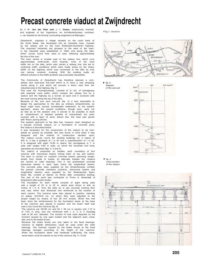
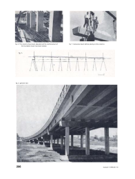
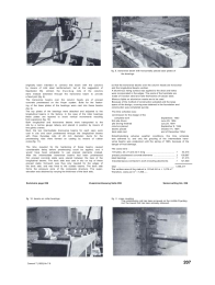
Precast concrete viaduct at Zwijndrechtby ir W. van der Ham and ?r J. Visser, respectively memberand engineer of the 'Ingenieurs- en Architectenbureau voorheenJ. van Hasselt en de Koning' (consulting engineers) at Nijmegen.Zwijndrecht, originally a village situated on the north bank ofthe Oude Maas, has developed into an industrial town, crossedby the railway and by the main Rotterdam-Dordrecht highway.The important industries are grouped to the west of the town,in the industrial area established in 1949, and along the dike,which curves round from west to east, following approximatelythe line of the river.The town centre is located east of the railway line, which runsapproximately north-south. Until recently, most of the localtraffic ran on the dike, which also carries a railway line; this led toconfusing traffic conditions which were made worse by the heavytraffic on the highway which was connected to the dike by onlyone narrow, nonlevel, crossing. With the existing roads anefficient solution to the traffic problem was practically impossible.The Community of Zwijndrecht has therefore planned a com-pletely new east-west link-road which is to have a new shoppingcentre along it, and which will provide a direct road from theindustrial area to the highway (fig. I).This road, the 'Koninginneweg', consists of 3-i km. of carriagewaywith separate cycle paths, which crosses the railway line by aviaduct and the highway by a tunnel; at each end it connects withthe road running along the top of the dike.Because of the very poor sub-soil (fig. 2) it was impossible todesign the approaches to the dike as ordinary embankments, asthese might have caused considerable settlement. At the easternapproach, where the subsoil conditions, though poor, were notas bad as at the western end, it proved to be possible to buildan embankment of stacked packets of compressed dry peat,covered with a layer of sand. Above this, the road was pavedwith 'Waco' paving stones.The western approach to the dike has, however, been designed asa precast concrete viaduct, on a foundation of concrete piles;this viaduct is described below.It was necessary for the construction of the viaduct to be com-pleted as quickly as possible; this was borne in mind when it wasdesigned and the method of construction decided upon.The viaduct curves round the existing buildings on a radius of400 m; it has a gradient of I in 30 and a superelevation of I in 80.It is designed with eight 15.60 m spans; the carriageway is 7 mwide with verges 0.80 m wide, on which the handrails and lampstandards are mounted (figs. 3, 4 and 5).The viaduct is supported on trestles, each consisting of fourcolumns with transverse beams linking them at top and bottom.The deck is carried on l-section concrete beams spanning longitu-dinally from trestle to trestle. At alternate trestles the I-beamsare carried on roller bearings. Two in situ prestressed concretetransverse beams in each span brace the longitudinal beams.The concrete piles were supplied by the Schokindustrie Limited,the precast concrete members (columns, transverse beams andlongitudinal beams) were supplied by the Nederlandse Span-beton Mij. Limited at Alphen on Rhine after competitive bidding.The rest of the work was contracted to Firma A. Buitendijk ofZwijndrecht after public tender.The foundation for each trestle consists of eight raking pileswith a length of 20 m to 22 m, which were driven in with anincline of I in 8. Over the piles an in situ concrete working floorwas cast, which was thickened and reinforced at the location ofeach column. The columns were then placed in position, standingon plates, 30?30?8 cm, on which they were adjusted to theproper height by means of two 26 mm screws. When this hadbeen done the reinforcement for the foundation beam at the baseof the columns was placed in position and the beam itself wascast in situ round the columns (fig. 6).The columns are 30?50 cm and 40 ? 50 cm in section and 1.10 mto 3.54 m long, and are reinforced with I, 2, 3 or 4 Dywidagrods of 26 mm. diameter. The number of rods used depends on themoment caused by one span loaded and the adjacent span unloa-ded, and to the brake forces.Because the brake forces are only taken to the fixed bearings,columns of slighter dimensions could be used under the rollerbearings. The moment caused by the brake forces at the fixedbearings changes according to the height of the columns.When the foundation beam had hardened sufficiently, the trans-verse beam could be placed on top of the columns (fig. 7). It had fig.1. situation fig. 2.diagramof the sub-soil fig. 3.cross-sectionof the viaductCement 7 (1955) Nr 7-8 205fig. 6. The columns have been adjusted and the reinforcement ofthe foundation beam has been twisted.fig. 7. transverse beam before placing on the columnsfig. 5. general view206 Cement 7 (1955) Nr 7-8fig. 9. transverse beam with horizontally placed base plates ofthe bearingsoriginally been intended to connect this beam with the columnsby means of mild steel reinforcement, but at the suggestion ofSpanbeton Mij. Limited, the D ywi da g rods of the columnswere instead extended through the transverse beam to providea fixed joint (fig. 8).The transverse beams over the column heads are of precastconcrete prestressed on the Hoyer system. Bolts for the fasten-ing of the base plates of the bearings were cast into these beams(fig? 9).The top plates of the bearings were attached and adjusted to thelongitudinal beams in the factory; in the case of the roller bearingsthese plates are tapered to avoid vertical movements resultingfrom expansion (fig. 10).Both longitudinal and transverse beams were transported to thesite by a narrow gauge railway and placed in position by means oftwo gantry cranes.Next, the two intermediate transverse beams for each span werecast in situ and each prestressed through the longitudinal beamswith three Dywidag rods of 26 mm diameter; ducts for theprestressing rods were formed on casting by means of rubbercores (fig. 11).The time required for the hardening of these beams causedconsiderable delay before prestressing could be applied, and itwould have been advisable to use precast elements instead.After the intermediate transverse beams had been prestressedthin precast concrete slabs were placed between the tops of thelongitudinal beams. The deck slab was cast in situ on top of theseprecast slabs; formwork was thus only needed for the edges ofthe deck slab, and was fixed to the outside beams. The deck slabforms the pressure zone of the composite structure. The super-elevation was obtained by varying the thickness of the deck slab,so that the transverse beams over the column heads are horizontaland the longitudinal beams vertical.A bituminous riding surface was applied to the deck and kerbswere incorporated in the edges. The posts of the handrails aremade of l-section steel and rails themselves of tubular steel.Mercury lights on aluminium masts are to be used.Because of the method of construction adopted and the largespans of the design, a saving was obtained in the foundation andconstruction was completed quickly.The time schedule was:commission for the design of thecomplete work September, 1953first pile driven June 29, 1954pile driving finished July 29, 1954columns placed September 9, 1954beams placed October 14, 1954deck slab cast end of December 1954Notwithstanding adverse weather conditions, this time schedulewas adhered to, and only the grouting of the intermediate trans-verse beams was postponed until the spring of 1955, because of thedanger of frost damage.The costs were :104 piles, 20, 21 and 22 m long ............................................ f 43,315precast prestressed concrete elements .................................. 100,087steel bearings ......................................................................... f 21,315miscellaneaous contractor's work including abutments f 121,500total ......................................................................................... f 286,217The surface area of the viaduct is 125x8.60 m = 1,075 m2.Therefore, costs per m2= f 266.--.Sommaire page 208 Zusammenfassung Seite 208 Samenvatting blz, 208flg. 10. beams on roller bearings fig. I I. cross couplingThe prestressing rod has been screwed on the middle Dywidagrod; the lowest rod has been already stressed.Cemenl 7 (1955) Nr 7-8 207
Reacties