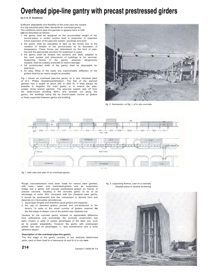
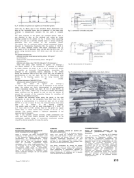
Overhead pipe-line gantry with precast prestressed girdersby ir A. D. EeckhoutSufficient adaptability and flexibility of the outer pipe-line systemof a big industrial plant often demands an overhead-gantry.The conditions which pipe-line gantries in general have to fulfilcan be described as follows:1. the gantry shall be designed on the accumulated weight of theservice-pipes, a certain surplus load in proportion to expectedfuture expansion of the pipe-line system, snowload and wind;2. the gantry shall be calculated to take up the forces due to thevariation of lengths of the service-pipes by its fluctuation oftemperature. These forces are determined by the kind of pipe-line and the appropriate provision for expansion in same;3. the gantry shall be divided into sections and bays, adapted tothe road system and dimensions of buildings to be serviced.Supporting frames of the gantry, wherever dangerouslysituated, shall be suitably protected to restrict damage;4. full unobstructed width of the gantry shall be disposable forpipe-lines;5. for easy fitting of the pipes any inpreventable deflection of thegirders shall be as nearly naught as possible.Fig. I shows an overhead pipe-line gantry on a new industrial plantof N.V. Philips Gloeilampenfabrieken. The first of the plannedgantries has a length of about 200 m (655 ft). It shall always bepossible to lengthen the main gantry or to extend the pipe-system along branch gantries. The pipe-line system sets off fromthe boiler-house (building MHC) and spreads out along thegantry, the buildings being fed by branch-pipes carried by girdersor freely supported between gantry and building.fig. 2. framework c of fig. I, of in situ concretefig. I. side view and plan of an overhead gantryRough cost-estimations have been made for various steel gantries,with truss-, plate- and Vierendeel-girders and as suspensionbridge and a gantry with precast prestressed girders on frames ofprecast concrete, resulting in the concrete gantry to be at anadvantage of some 30% compared with the cheapest steel gantry.It should be emphasized that this comparison is derived from anddepends on 2 favourable coincidences;1. equal span lengths and therefore equal girders and supports,2. the use of standard girders precast and pre-tensioned in thefactory. In spite of the small number of girders required forthe first stage of design, cost of the girders was relatively low.Tenders for the concrete gantry showed no appreciable differencefrom estimations and accordingly the concrete construction hasbeen chosen in spite of certain advantages of the steel one, suchas its greater adaptability. However the gantry with prestressedgirders has also its advantages i.c. less maintenance and a moreattractive aspect.Description of the overhead pipe-line gantryThe first stage of the gantry consists of two statically determinedparts, each of them fixed to a framework (A and ?) of in situ con-Cement 7 (1955) Nr 7-8fig. 3. supporting frames, cast on a centrallysituated place in vertical shuttering214fig. 4. windties and girders act together as Vierendeel-girdersCrete (fig. 2). Being rigid in two directions these frameworks cantake up the horizontal forces due to expansion of the pipes andwindload. A dilatation-joint between the two parts is situatedat .The other supports of the gantry are 2-hinged frames, rigid inone direction to take up the windload and acting as rockerbearings parallel to the girders. As fig. 3 shows, these supportingframes are cast on a centrally situated place in vertical shuttering.Afterwards they are erected on the foundation blocks.The girders are, as mentioned before precast prestressed beams,delivered by 'Nederlandse Spanbeton Mij', the girders of 16,25 m(53' 5") being standard beams l-NP 60/24, prestressed with 32wires diam. 5 mm of Samesco steel 130/165, and the 20 m (64' 19")girders being standard beams l-NP 80/32 each with 58 bars diam.5 mm.The allowed stresses are:effective concrete compressive bending stress: ISO kg/cm2(2,150 Ib/sq.in.)initial concrete compressive bending stress: 195 kg/cm2(2,800 Ib/sq.in.)effective wire stress, steel 130/165: 86 kg/mm2(55 tons/sq.in.)initial wire stress, steel 130/165: III kg/mm2(71 tons/sq.in.)The lateral stiffness of the construction to windload is obtainedby prefab windties. As shown in fig. 4 and 5, windties and girdersact together as horizontal Vierendeel-girders, transmitting thewindload to the supporting frames. Moments in the windtiehaving the maximum value of 815 kgm (5,910 Ibft), can be taken bypost-tensioning of one bar diam. 26 mm of Rheinhausen steel80/105, to the Dywidag system; this bar being inserted aftererection of the windtie.The allowed stresses of steel 80/105 are:effective wire stress 52 kg/mm2(33 tons/sq.in.)initial wire stress 68 kg/mm2(43 tons/sq.in.)To transmit the horizontal forces due to expansion of the service-pipes, the girders are firmly interconnected by post-tensioningof two crosswisely inserted bars diam. 26 mm of steel 80/105, asshown in fig. 6 and 7, Note in fig. 6 the use of double steel bearingplates anchored into the girders as well as onto the frames, toprevent the concrete of the supporting frames for crumbling offby shifting of the girders over same.To transmit the horizontal forces along the gantry to the rigidframeworks (A and ?), the end-girders have been fixed onto thesupports by post-tensioning of a vertical bar diam. 26 mm of steel80/105, to a load of about 25 tons, the horizontal forces thus beingheld up by friction of the bearing surfaces.The service pipes are laid on steel cross-beams of 2 E-NP 10(2.4'' C)on 3.20 m (10'6") centres, fixed on the girders by copperinserts diam. V', these inserts being provided at 80 cm (2' 7")intervals. This system allowed a maximum adaptability of thepipe-lines laid on the gantry.Thus in situ concrete, precast concrete, prefab prestressed con-crete and steel cross beams provided the components for anaesthetically justified design of economical construction posses-sing all the desired properties of a pipe-line gantry.fig. 5. connection of windtie and girderfig. 6. interconnection of the girdersfig. 7. pretensioning the crosswisely inserted bars diam. 26 mmSAMENVATTINGBovengrondse leidingbrug van gestandaardi-seerde voorgespannen prefab liggersdoor ir. . D. EeckhoutNadac is nagegaan, aan welkG voorwaarden eenleidingbrug in het algemeen moet voldoen, wordter een beschrijving gegeven van een leidingbruggeconstrueerd uit gestandaardiseerde voorge-spannen prefab liggers op jukken, die in de langs-richting van de brug als pendelstijlcn werken,terwijl de horizontale langskrachten wordenopgenomen door vaste portaalconstructies. Doorde combinatie van in het werk gestorte beton, opeen centrale plaats vooraf gestorte jukken,voorgespannen prefab liggers en windverbanden,en stalen dwarsdragers voor oplegging van depijpen is een economische en aesthetisch verant-woorde constructie verkregen, die aan de gesteldeeisen heeft voldaan.SOMMAIREPont pour conduites ex?cut? en poutres pr?-fabriqu?es standardis?esM. A. D. Eeckhout, ing?nieurApr?s avoir stipul? les conditions que doiventremplir les ponts destin?s ? porter des conduites.une description est donn?e d'un cel pont, faitd'?l?ments pr?fabriqu?s pr?contraints. Ce ponts'appuie sur des pal?es, travaillant comme pendu-les dans le sens longitudinal. Des portiques fixesprennent soins des r?actions horizontales.Une bonne coordination de travaux de naturesdiverses, b?ton coul? sur place, pal?es b?tonn?essur un chantier central, poutres et contrevente-ments pr?fabriqu?s et pr?contraints, traverses enacier supportant les tuyauteries, a contribu? ? unesolution ?conomique et esth?tique qui a r?pondu? tous les points de vue aux exigences.ZUSAMMENFASSUNGBr?cke f?r oberirdische Leitungen aus nor-malisierten praefabrizierten Tr?gern ausSpannbetonvon Dipl.-Ing. A. D. EeckhoutNach der Feststellung, welche Bedingungen eineLeitungsbr?cke im Allgemeinen erf?llen muss.wird eine aus normalisierten vorgespannten Tr?-gern erbaute Leitungsbr?cke beschrieben. Die Auf-lagerjoche wirken in der L?ngenrichtung als Pen-delst?tzen: die horizontale L?ngskr?fte werdenvon kr?ftigen Portalen aufgenommen. Durch dieKombination des an Ort und Stelle hergestelltenBetons mit den auf einem zentral gelegenen Platzpraefabrizierten Jochen, den praefabrizierten vor-gespannten Tr?gern und Windverb?nden, undschliesslich den st?hlernen Quertr?gern zur Unter-st?tzung der Leitungsrohre wurde eine ?konomi-sche und ?sthetisch gerechtfertigte Konstruktiongeschaffen, die allen an sie gestellten Anforde-rungen gerecht wird.Cemenl 7 (19S5) Nr 7-8 215
Reacties