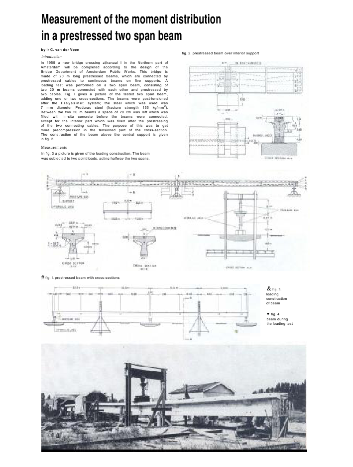
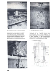
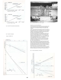
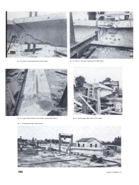
Measurement of the moment distributionin a prestressed two span beamby ir C. van der VeenIntroductionIn 1955 a new bridge crossing zijkanaal I in the Northern part ofAmsterdam will be completed according to the design of theBridge Department of Amsterdam Public Works. This bridge ismade of 20 m long prestressed beams, which are connected byprestressed cables to continuous beams on five supports. Aloading test was performed on a two span beam, consisting oftwo 20 m beams connected with each other and prestressed bytwo cables. Fig. I gives a picture of the tested two span beam,adding one or two cross-sections. The beams were post-tensionedafter the Freyssi net system; the steel which was used was7 mm diameter Produrac steel (fracture strength 155 kg/mm2).Between the two 20 m beams a space of 20 cm was left which wasfilled with in-situ concrete before the beams were connected,except for the interior part which was filled after the prestressingof the two connecting cables. The purpose of this was to getmore precompression in the tensioned part of the cross-section.The construction of the beam above the central support is givenin fig. 2.MeasurementsIn fig. 3 a picture is given of the loading construction. The beamwas subjected to two point loads, acting halfway the two spans.fig. 2. prestressed beam over interior supportfig. I. prestressed beam with cross-sectionsfig. 3.loadingconstructionof beam fig. 4beam duringthe loading testfig. 5. hydraulic jack with pressure box atone of the end supports fig. 7. strain gages fixed on concrete of the beamThe loads were exerted with aid of hydraulic jacks, acting againstthe two loading frames. Hydraulic jacks were also placed belowthe supports of the beam in order to ascertain an equal level ofthe three supports during the test. This purpose was attainedwithin the limit of one mm at a maximum.In the two loading points and the three supports pressure boxeswere placed with electrical wire resistance strain gages in orderto measure the exerted forces and reactions with sufficientaccuracy.Moreover the deflection of the beam in several points was measu-red and in three cross-sections strain gages were applied tomeasure the strains in the beam during the test.The measuring boxes used for determining the exerted forceswere also employed, and in fact originally designed for thatpurpose, for measuring the forces in the cables during pre-stressing. With aid of them the actual prestress in the cables couldbe measured very accurately. Fig 8 gives a cross-section of thesemeasuring boxes; the darkened part was only used when mea-suring the exerted forces on the beam. The results of the prestressmeasurements for the two connecting cables are given in fig. 9.fig. 6. pressure box and hydraulic jack fig. 8. cross-section of pressure box188 Cernent 7 (1955) Nr 7-8fig. 9. results of the prestress measurementsfig. II. reaction of supportsCemenl 7 (1955) Nr 7-8fig. I0. prestressed beam over interior supportReactions and moment distributionsOf all measurements which were made only the reactions at thesupports and the moment distribution during the loading testare given here. The results are collected in the graphs of fig.II and I2.In fig. 11 the reactions at the supports are given as a function ofthe average load ? (Pl+Pr) on the beam. As Pl and Pr during thetest were not exactly equal, as appeared from a very accuratecalibration of the pressure boxes after the performance of thetest, there is some spreading in the results.The measured values which are represented by dots in fig. 11appear to ly approximately on two straight lines which intersectif ? (Pl+Pr) is equal to little less than ton, the beam beingdesigned for an aequivalent load Pl=Pr= I I ton. If plotted in themoment distribution graph in fig. 12 the measured points againcan be approximately replaced by two straight lines.In the elastic phase, up to ? (P/ +Pr) = 14 ton, the measuredreactions and moments correspond perfectly with the valuesaccording to the Clapeyron law. The latter are represented infig. I I and 12 by the dotted lines.Beyond the elastic phase the increase of the moment over theinterior support diminishes with increasing load; there remainshowever a linear relationship between exerted load and moment.This means that the connection of the two original beams abovethe central support takes more or less the function of a hinge.The increase of the moment is about 23% of what it should havebeen if the Clapeyron law was valid In this phase.On the contrary the moments at mid span of the two connectedbeams are about 43% more than according to the Clapeyron law.During the loading test the first fissure in the beam above thefig. 12. moment distribution in the beam189fig. 13. beam in one loading point after failure fig. 14. beam in the other loading point after failurefig. 15. upper side of beam over interior support after failure fig. 16. anchorages after failure of the beamfig. 17. prestressed beam after failure190 Cernent 7 (1955) Nr 7-8central support appeared at a load of about 11 ton. It consistedof two cracks in the joints between the beams and the in-situconcrete. These cracks extended rapidly downwards at increasedloading of the beam, without leading to failure. At mid span thefirst cracks appeared at a load ? (Pl+Pr) = 23 ton. Ultimatefailure of the beam took place under one of the loading points(Pr) when a moment of little less than 200 tm had been reached.Thebending moment over the interior support was then nearly120 tm.When computing the theoretical ultimate failure moments outof the cross-sections of the beam over the central support andat mid span, it appears that in both cases the measured valuesare within a range of 3% exactly corresponding to the theoreticalvalues. This means that at the moment of failure all three cross-sections, above the interior support and at both mid spans, areused to their maximum resistance. This points to a behaviourof the two span beam according to the theory of plasticity, whichstates that a redundant structure fails when all redundantsand one nonredundant section have attained their limitingvalues (limit design).Attention may bo drawn to the fact, that beyond the elasticphase the moments over the central support and at both midspanschange rectilinearly with the exerted loads and meet simul-taneously the maximum resistance in the various cross-sections.It is as if the beam immediately beyond the elastic phase 'knows'the moment distribution at failure and takes the shortest way to it.SAMENVATTING SOMMAIRE ZUSAMMENFASSUNGMetingen van de moment-verdeling in eenvoorgespannen balk met 2 overspanningendoor ir C. van der VeenEen korte beschrijving wordt gegeven van de ver-richting en de resultaten van de proefbelasting totbreuk op een voorgespannen balk met een totalelengte van 40,20 m. Gedurende de proef werdende drie steunpunten m. b. v. hydraulische vijzelsop dezelfde hoogte gehouden. De reacties en deuitgeoefende belastingen werden gemeten metbehulp van dynamometers. De gemeten moment-verdeling tijdens de elastische fase bleek geheel ?novereenstemming te zijn met de berekende waar-den overeenkomstig de Wet van Clapeyron.Voorbij de elastische fase werden de momenten inde balk boven de middenondersteuning met on-geveer een ? van de Clapeyron waarden geredu-ceerd terwijl de momenten in het midden vande overspanning 43% stegen boven de Clapeyronwaarden. Breuk trad op in het midden van deoverspanning van de balk. De momenten in de balkop de 2 belascingpunten waren gelijk aan de theo-retische maximum weerstand.Essais sur la r?partition des moments fl?chis-sants dans une poutre pr?contrainte ? deuxtrav?es continuespar M. C. van der Veen, ing?nieurDescription des essais et des r?sultats obtenusd'un essai ? la rupture d'une poutre pr?contrainted'une ongueur totale de 40.20 m. Au cours del'essai, les trois appuis ont ?t? maintenus, ? l'aidede v?rins hydrauliques, ? un niveau constant. Lesr?actions d'appuis, ainsi que les charges exerc?es,ont ?t? mesur?es ? l'aide de dynamom?tres. Lar?partition des moments fl?chissants pendant laphase ?lastique correspondait aux valeurs calcu-l?es selon la loi de Clapeyron.Au del? de la phase ?lastique le moment sur appuibaissait jusqu'? ? de la valeur de Clapeyron,tandis que les moments en trav?e augmentaientjusqu'? 43% au dessus des moments, calcul?sd'apr?s la m?thode ?lastique. La rupture s'estfaite en trav?e. Les moments maximum dans lapoutre au droit des 2 charges correspondaient ?la r?sistance maximum calcul?e.Messungen der Momentenverteilung ineinem Balken aus Spannbeton ?ber 2 Oeff-nungenvon Dipl.-Ing. van der VeenDer Verfasser dieses Artikels gibt eine Beschrei-bung vom Verlauf und die Resultate einer Belas-tungsprobe bis zum Bruch eines Balkens aus Spann-beton mit einer Gesamtl?nge von 40,20 m. W?h-rend der Belastungsprobe wurden die 3 St?tz-punkte mithilfe hydraulischer Pressen auf ihrerurspr?nglichen H?he gehalten. Die aufgebrachteBelastung und die Auflagerdr?cke wurden mit-hilfe von Dynamometers gemessen.W?hrend der elastischen Phase kam die gemesseneMomentenverteilung mit der nach dem Gesetzevon Clapeyron berechneten volkommen ?berein.Nach Ueberschreitung der elastischen Phase wur-de das Moment ?ber dem Zwischenst?tzpunktgegen?ber dem theoretischen Wert nach Clapey-ron um 25% vermindert, w?hrend die gr?sscenpositiven Momente ihre theoretischen, nachClapeyron berechneten Werte um 43% ?ber-schritten haben. Der Bruch fand in der Feldmitcestatt,Mededeling betreffende 2e Internationale Congres Voorgespannen BetonIn de eerstvolgende afleveringen van 'Cement' wordt opgenomen een samenvatting in de Nederlandse taal vande tijdens bovengenoemd congres gehouden lezingen c.q. uitgebrachte rapporten.Cement 7 (1955) Nr 7-8 191
Reacties