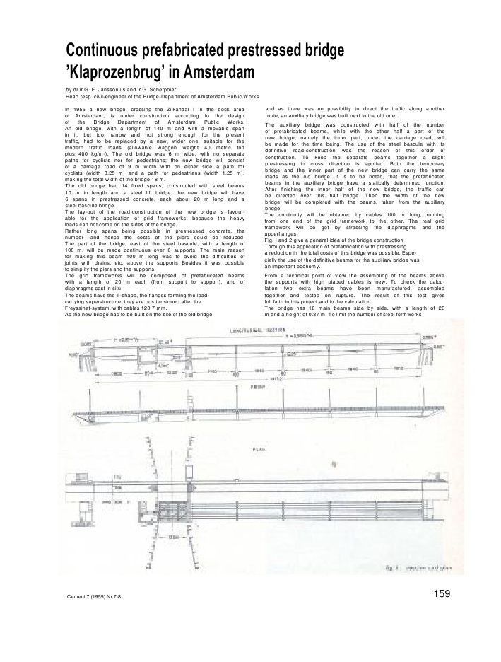
Continuous prefabricated prestressed bridge'Klaprozenbrug' in Amsterdamby dr ir G. F. Janssonius and ir G. ScherpbierHead resp. civil-engineer of the Bridge-Department of Amsterdam Public WorksIn 1955 a new bridge, crossing the Zijkanaal I in the dock areaof Amsterdam, is under construction according to the designof the Bridge Department of Amsterdam Public Works.An old bridge, with a length of 140 m and with a movable spanin it, but too narrow and not strong enough for the presenttraffic, had to be replaced by a new, wider one, suitable for themodern traffic loads (allowable waggon weight 40 metric tonplus 400 kg/m-). The old bridge was 6 m wide, with no separatepaths for cyclists nor for pedestrians; the new bridge will consistof a carriage road of 9 m width with on either side a path forcyclists (width 3,25 m) and a path for pedestrians (width 1,25 m),making the total width of the bridge 18 m.The old bridge had 14 fixed spans, constructed with steel beams10 m in length and a steel lift bridge; the new bridge will have6 spans in prestressed concrete, each about 20 m long and asteel bascule bridgeThe lay-out of the road-construction of the new bridge is favour-able for the application of grid frameworks, because the heavyloads can not come on the sides of the bridge.Rather long spans being possible in prestressed concrete, thenumber -and hence the costs of the piers could be reduced.The part of the bridge, east of the steel bascule, with a length of100 m, will be made continuous over 6 supports. The main reasonfor making this beam 100 m long was to avoid the difficulties ofjoints with drains, etc. above the supports Besides it was possibleto simplify the piers and the supportsThe grid frameworks will be composed of prefabricated beamswith a length of 20 m each (from support to support), and ofdiaphragms cast in situThe beams have the T-shape, the flanges forming the load-carrying superstructure; they are posttensioned after theFreyssinet-system, with cables 120 7 mm.As the new bridge has to be built on the site of the old bridge,and as there was no possibility to direct the traffic along anotherroute, an auxiliary bridge was built next to the old one.The auxiliary bridge was constructed with half of the numberof prefabricated beams, while with the other half a part of thenew bridge, namely the inner part, under the carriage road, willbe made for the time being. The use of the steel bascule with itsdefinitive road-construction was the reason of this order ofconstruction. To keep the separate beams together a slightprestressing in cross direction is applied. Both the temporarybridge and the inner part of the new bridge can carry the sameloads as the old bridge. It is to be noted, that the prefabricatedbeams in the auxiliary bridge have a statically determined function.After finishing the inner half of the new bridge, the traffic canbe directed over this half bridge. Then the width of the newbridge will be completed with the beams, taken from the auxiliarybridge.The continuity will be obtained by cables 100 m long, runningfrom one end of the grid framework to the other. The real gridframework will be got by stressing the diaphragms and theupperflanges.Fig. I and 2 give a general idea of the bridge constructionThrough this application of prefabrication with prestressinga reduction in the total costs of this bridge was possible. Espe-cially the use of the definitive beams for the auxiliary bridge wasan important economy.From a technical point of view the assembling of the beams abovethe supports with high placed cables is new. To check the calcu-lation two extra beams have been manufactured, assembledtogether and tested on rupture. The result of this test givesfull faith in this project and in the calculation.The bridge has 16 main beams side by side, with a length of 20m and a height of 0.87 m. To limit the number of steel formworksCement 7 (1955) Nr 7-8 159the shape of every beam has been made nearly the same Thedevelopment of the cables in the various spans is of coursedifferent. So for the six spans (5 statically indeterminate andI statically determinate) 96 beams were needed, making, withthe two beams for the test, together 98 beams to be manufactured.With only two steel formworks and 4 beds these beams havebeen manufactured with steam curing in only 16 weeks.The cross-section of the beams has a T-shape, with a web gettingthicker towards the bottom. The purpose of this was that therewould be in the lower part of the beam enough space for thecables, whereas for the bending up of the cables at the ends nodouble bends were needed. Besides the formwork was moresimple and it was possible to cast with a dry concrete.The construction of the beam above the supports is given infig. 3.The prefabricated beams, which will be built together as to formthe main beams of 100 m, are placed on the supports with aspace of 0,20 m between them Of these joints between thebeam-ends only the lower and the upper part (0,20 m each)is cast in situ to begin with Then the two continuity-cables of100 m are stressed in each main beam; for practical reasons thesecables lie in a gutter and not in a tube.These two cables give in the beams a stress in the neutral axisas is shown for a beam with fixed ends in fig 4. As the threeinner spans have practically fixed ends, this effect holds for thesespans too. In the two side spans one of the two cables is bentdown, so as also to get here the stress in the neutral axis; wherea cable bends down at one end, this one is straight at the otherend, thus diminishing the friction.After stressing these two cables the joints will be cast full in situ.The joint is then strong enough to withstand the negative bend-ing moment, consequent to the mobile load.It would also have been possible to connect the beams with'hat-cables'; as however these cables have drawbacks owing totheir short length and their high friction, the use of the longcables has been preferred. As can be seen in fig. 2 the staticallyindeterminate beams have one cable more than the staticallydeterminate beams. However, the avoidance of open jointsabove the supports and the simplification of these supports wasof such importance that a greater use of steel has been acceptedThe beams will rest via hair-felt on the supports. The innersupports are constructed in such a way that they have the functionof a big, somewhat stiff roller.fig. 5. test-loading of continuous beam160 Cemenl 7 (1955) Nr 7-8To conclude with is a picture of the test-loading given in fi-gure 5. The beam was subjected to two point loads, actinghalfway the two spans. The loads were exerted with aid ofhydraulic jacks, acting against the two loading frames. Hydraulicjacks were also placed below the supports of the beams in orderto ascertain an equal level of the three supports during thetest. In the two loading points and the three supports measuringboxes were placed with electrical wire resistance strain gagesin order to measure the exerted forces and reactions withsufficient accuracy. Moreover the deflection of the beam inseveral points was measured and in three cross-sections strain-gages were applied to measure the strains in the beam duringthe test.Measuring boxes were used for determining the forces exertedby the anchorages of the cables on the concrete of the beams;they were in fact originally designed for that purpose. With aidof them the actual prestress in the cables was measured veryaccurately.SAMENVATTINGKlaprozenbrug te Amsterdamdoor dr ir G. F. Jcjnssoniusen ir G. ScherpbierDe bouw van de brug vindc als volgt plaats:I. montage van de 48 liggers in de hulpbrug, betonstorten tussen de bovenflenzen en gering voor-spannen in dwarsrichting met 18 kabelj;2. montage van 48 liggers in het midden van denicuwe brug, betonneren van de voegen van elkeligger, continuTteitsvoors panning aanbrengenmet 2 kabels in de bovenflens, betonneren vande dwarsliggers en tussen de bovenflensen. ge-ringe voorspanning in dwarsrichting aanbren-gen met I kabel in elk van de 21 dwarsliggers;3. montage van 48 liggers van de hulpbrug aanweerszijdcn van de nieuwe brug, betonnerenvan de voegen, continuiteitsvoorspanning aan-brengen, betonneren van de dwarsliggers entussen de bovenflenzen, tenslotte completevoorspanning in dwarsrichting aanbrengen;4. een proefbelasting op ware grootte als controlevan de berekening op een doorgaande balk, uit2 gewone balken door voorspanning samen-gesteld.SOMMAIREPont 'Klaprozenbrug' a Amsterdampar M. G. F. Janssonius, ing?nieur-docteuret M. G. Scherpbier, ingenieurLe pont en question doit etre execute comme suit:1. Assemblage de 48 poutres destinies au pontauxiliaire, coulage du bdton entre les membru-res superieures, precontrainte transversalc par-tielle par 18 cables.2. Assemblage de 48 poutres destinees a la partiedu milieu du nouveau pont, betonnage desjoints de chaque poutre; precontrainte de con-tinuity par 2 cables dans la membrure supe-rieure, coulage des entretoises et des espacesentre les membrures supeVieuros; precon-trainte partielle transversale a I'aide d'unseulcable dans chacune des 21 entretoises.3. Assemblage de 48 poutres du pont auxiliairedes deux cotes du nouveau pont. betonnagedes entretoises et de la dalle comprise entre lesmembrures superieures; finalement precon-trainte transversale complete.4. Un essai de charge effectue sur une poutrehyperstatique constitute par 2 poutres ordi-naires, assemblies par precontrainte.ZUSAMMENFASSUNGBriicke 'Klaprozenbrug' in Amsterdamvon Dr. Ir. G. F. Jonssoniusund Dipl.-lng. G. ScherpbierReihenfolge der auszufuhrenden Arbeiten:1. Montage von 48 Tragern in der Hilfsbrucke;Einbringen des Betons zwischen den oberenFlanschen und massiges Vorspannen in Quer-richtung mit 18 Kabeln.2. Montage von 48 Tragern im Mittelstreifen derneuen Brucke; Ausbetonieren der Fugen zwi-schen alien Tragern; Anbringen der Kontinui-tats-Vorspannung durch Anspannen zweierKabel im oberen Flansch; Betoniercn derQuertrager und Einbringen des Betons zwi-schen den oberen Flanschen. Massiges Vor-spannen in Querrichtung mit einem Kabel injedem der 21 Quertrager.3. Montage von 48 Tragern der Hilfsbrucke zubeiden Seiten der neuen Brucke, Ausbetonierender Fugen; Anbringen der Kontinuitats-Vor-spannung, Betonieren der Quertrager und Ein-bringen des Betons zwischen den oberen Flan-schen; endgultiges Vorspannen in Querrich-tung.4. Belastungsprobe einer Konstruktion im natiir-lichen Maszstab, bestehend aus zwei gewdhn-lichen. durch Vorspannung zu einem durch-laufenden Trager zusammengefugten Balken,ausgefiihrt zur Kontrolle der Berechnung.Het uitvoeren van betonwerken bij lage temperaturenVan 13 t/m 18 Februari 1956 zal te Kopenhagen een inter-nationaal symposium 'Winter Concreting, Theory and Practice'worden gehouden.Inlichtingen en voorlopig programma aan te vragen bij: TheOrganizing Secretary RILEM Symposium 1956, c/o DanishNational Institute of Building Research, Borgergade 20, Kopen-hagen, K.Kosten van inschrijving, incl. alle technische publicaties dochexclusief excursies, bij inschrijving voor I October 1955, voorleden van de Reunion Intern, des Laboratoires d'Essais et deRecherches sur les Materiaux et les Constructions, RILEM,50 Deense Kr. en na I October 75 Deense Kronen; niet-leden75 resp. 100 Deense Kronen. Begeleidende familieleden, diede publicaties niet zullen ontvangen, 20 resp. 30 DeenseKronen. (I Deense Kroon is ongeveer 55 cent.)Voorlopig programma:13 en 14 Februari. Theoreti&the onderwerpen:A. Definitievan klimatologische omstandigheden en hun repro-ductie in het laboratorium,Bl. Laboratoriumproeven voor de vaststelling van de weer-stand van beton tegen bevriezing,BII. De invloed van de temperatuur op het verhardingsproces,C. Weerstand van beton in vroege stadia tegen vorst.15 en 16 Februari. Practische onderwerpen:D. Keuze van materiaal, verwarming en isolatie,E. Betonwerk op de bouwplaats in de winter.17 en 18 Februari. Excursies naar bouwwerken in Kopenhagen,Malmo en Lund.Cemenl 7 (1955) Nr 7-8 161
Reacties