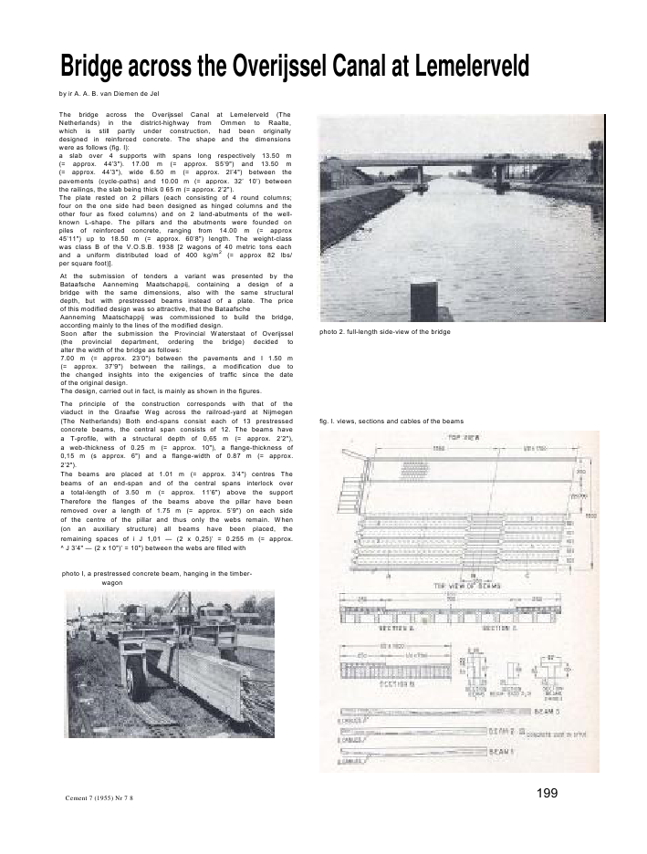
Bridge across the Overijssel Canal at Lemelerveldby ir A. A. B. van Diemen de JelThe bridge across the Overijssel Canal at Lemelerveld (TheNetherlands) in the district-highway from Ommen to Raalte,which is still partly under construction, had been originallydesigned in reinforced concrete. The shape and the dimensionswere as follows (fig. I):a slab over 4 supports with spans long respectively 13.50 m(= approx. 44'3"). 17.00 m (= approx. S5'9") and 13.50 m(= approx. 44'3"), wide 6.50 m (= approx. 2I'4") between thepavements (cycle-paths) and 10.00 m (= approx. 32' 10') betweenthe railings, the slab being thick 0 65 m (= approx. 2'2").The plate rested on 2 pillars (each consisting of 4 round columns;four on the one side had been designed as hinged columns and theother four as fixed columns) and on 2 land-abutments of the well-known L-shape. The pillars and the abutments were founded onpiles of reinforced concrete, ranging from 14.00 m (= approx45'11") up to 18.50 m (= approx. 60'8") length. The weight-classwas class B of the V.O.S.B. 1938 [2 wagons of 40 metric tons eachand a uniform distributed load of 400 kg/m2(= approx 82 lbs/per square foot)].At the submission of tenders a variant was presented by theBataafsche Aanneming Maatschappij, containing a design of abridge with the same dimensions, also with the same structuraldepth, but with prestressed beams instead of a plate. The priceof this modified design was so attractive, that the BataafscheAanneming Maatschappij was commissioned to build the bridge,according mainly to the lines of the modified design.Soon after the submission the Provincial Waterstaat of Overijssel(the provincial department, ordering the bridge) decided toalter the width of the bridge as follows:7.00 m (= approx. 23'0") between the pavements and I 1.50 m(= approx. 37'9") between the railings, a modification due tothe changed insights into the exigencies of traffic since the dateof the original design.The design, carried out in fact, is mainly as shown in the figures.The principle of the construction corresponds with that of theviaduct in the Graafse Weg across the railroad-yard at Nijmegen(The Netherlands) Both end-spans consist each of 13 prestressedconcrete beams, the central span consists of 12. The beams havea T-profile, with a structural depth of 0,65 m (= approx. 2'2"),a web-thickness of 0.25 m (= approx. 10"), a flange-thickness of0,15 m (s approx. 6") and a flange-width of 0.87 m (= approx.2'2").The beams are placed at 1.01 m (= approx. 3'4") centres Thebeams of an end-span and of the central spans interlock overa total-length of 3.50 m (= approx. 11'6") above the supportTherefore the flanges of the beams above the pillar have beenremoved over a length of 1.75 m (= approx. 5'9") on each sideof the centre of the pillar and thus only the webs remain. When(on an auxiliary structure) all beams have been placed, theremaining spaces of i J 1,01 -- (2 x 0,25)' = 0.255 m (= approx.^ J 3'4" -- (2 x 10")' = 10") between the webs are filled withphoto I, a prestressed concrete beam, hanging in the timber-wagonphoto 2. full-length side-view of the bridgefig. I. views, sections and cables of the beamsCement 7 (1955) Nr 7 8 199by the operation of prestressing. Though the design of shape ofthe cables in statical undeterminate structures and the compu-tation of tht 'parasitic moments', related to a given dispositionof cables, is not at all difficult (contrarily to an often assertedview-point), the absence of secondary moments certainly is notunattractive. By Che way, the parasitic moments generally reducethe statical undetermined moments due to dead and live loadconsiderably.As a result of the difference in the number of beams in the spansand of the cross-section of the concrete block above the inter-mediate supports the moment of inertia is not constant over thelength of the bridge. The moments of inertia of the central span,of the end-spans and above the pillars are in the ratio of I to1.08 to 1.8. The assumed ? of the concrete used for the slab castbetween the beams above the supports is 1/3 of the ? of theprestressed concrete. On account of the large moment of inertiaabove the pillars the positive moment is reducedThe beams, weighing 9 and 13 metric tons, have been ctrriedto the assembling-site by a timber-wagon, partly over steelstrips.partly over the already paved ramps.On photo I it is shown, how the beams have been hung in a frame.The frame could be jacked up by a hydraulic jack. Of course theframe had been constructed thus, that the vertical motion of thebeams was not limited by the stroke of the jack.The beams for the end-spans were carried to a couple of steel-joists at a fixed spot at the assembling-site, lowered betweenthese steel-joists and pushed into the final position by railsunderneath the auxiliary structure. The beams of the centralspan had to be lowered to the final position one by one Withoutcomplicated structures it has been possible to place three beamsa day.The structure with prefabricated prestressed concrete beamsmeant, as already said, a cheaper solution than the reinforcedconcrete structure. Bij organizing the job properly it is possibleto work at the same time at the beams and the substructureInstead of the time needed in the cage of a reinforced concretestructure to prepare the formwork and the reinforcement, theprestressed structure only requires time for the assembly of thebeams and the casting, of the slab between the flanges.In the reinforced concrete structure the roadway of the bridgewould have had a thickness of 0.65 m (= approx. 2'2"); in theprestressed structure the structural depth of the joists alsobecame 0.65 m (= approx. 2'2"). being the same as for thereinforced concrete type. However with regard to the reinforcedconcrete structure a saving of concrete of 48% (180 m3= approx.6350 cub. ft) could be realised. Apart from the saving of expensesfor concrete of the roadway this saving of concrete means asaving of the dead load of about 430 metric tons, representingan additional saving of 10 piles, with lengths ranging from 14.00m (= approx. 45' 11") to 18.50 m (= approx. 60'8").The reinforced concrete structure would have shown in side-view an uninterrupted line; in the using prestressed concretestructure, the side-view of the central span shows two inter-ruptions as a result of the shifting of the beams of the end-spanswith regard to those of the central span. How far the aestheticalphoto 5. part'y side-view of the bridgeappearance of the bridge has suffered by this, the reader mayjudge himself, by the pictures.The above mentioned interruption is not necessarily a result ofthe assembly; by choosing a different type of the side beam forthe central span it is possible to restore the uninterrupted line,without failing to comply with structural requirements.At the request of the Bataafsche Aanneming Maatschappij thepiles of the bridge have been made of pretensioned prestressedconcrete. The length of the piles varied from 14.00 m (= approx.45'11") to 18.50 m (= approx. 60'8"). A total of 60 piles werenecessary.The piles resisted the import during the transport from Alphen-on-Rhine (The Netherlands) and the driving without any failure.Some piles underwent a very severe test, which reinforcedconcrete piles would probably not have withstood. The prestressof the concrete of the piles was 40 kg/cm2(= approx. 570 psi).The amount of high tensile steel, used for the superstructure,was 39 kg/m3(= approx. 25 lbs/cub. ft) of concrete; the amountof mild steel for the superstructure was 18 kg/m3(= approx.1,14 lbs cub/ft) of concrete.The total amount of steel used in the superstructure was 7,900kg (= approx. 17,400 lbs) of high tensile steel and 3,400 kg(= approx. 7,500 lbs) of mild steel. The superstructure in rein-forced concrete about 55,500 kg (= approx. 122,000 lbs) ofmild steel would have been necessary. These differences, togetherwith differences of concrete, of the two structures say more thanany comparison of cost at the submission of tenders.SAMENVATTINGBrug te Lemelerveld over het OverijsselsKanaaldoor It A. A. B. van Diemen de leiDe brug over het Overijssels kanaal le Lemeler-veld is een over 4 steunpunten doorgaandcconstructie. Do brug bestaat uit 2 landhoofden en2 pijlers op palen en uit een bovenbouw vangeprefabriceerde betonbalken met bovcnflenzen,welke bovenflenzen, tezamen met er tussengestort beton, do rijvloer vormen.De balken van het ene veld worden verspringondt.o.v. de balken van het aansluitende veld ge-plaatst. Boven de tussensteunpunten grijpen debalken tussen elkaar; zij worden daar. nadat denodige betonvulling is gestort, door dwars-voorspanning tot een geheel vorcnigd.Parasitaire momenten, die bij het voorspannenvan statisch onbepaalde constructios optreden,blijven achterwege.Door dwarsvoorspanningskabols, gaande door deflenien van de balken en door de betonvullingontussen dezc flenzcn, wordt de dwarsvoorspanningin het dek bereikt, die nodig is voor de daarinoptredende momenten.Cement 7 (1955) Nc 7-8SOMMAIREPont a Lemelerveld sur le canal d'Overijsselpar M. A. A. E. van Diemen de lei, ingenieurCo pont continu de trois travees, dont le tablierconsiste de poutrcs en T prefabriques, solidariseesa I'aide de beton coule sur place ontre membruressuperieures. repose sur deux culees ct sur deuxpiles en riviere fondees sur pieux.Les poutres d'une travee s'entrelaccnt avec cellesde la travee voisine. au droit des appuis. La conti-nuity est obtenue a I'aide d'une precontraintetransversale sur appuis apres remplissage par be-ton des espaces entre les poutres.Ceci evite de tenir comptc des moments hyper-statiqucs engendres par une precontrainte longi-tudinale.La precontrainte transversale sert d'autre part aresister a la flexion transversale.ZUSAMMENFASSUNGDie Briicke zu Lemelerveld iiber den Over-ijssel'schen Kanalvon Dipl.-lng. A. A. B. von Diemen de leiDie Briicke iiber den Overijssel'schen Kanal zuLemelerveld ist eine iiber vier Stiitzpunkte durch-laufende Konstruktion. Sie stent auf Pfahlen undbesteht aus zwei Landwiderlagern, zwei Pfeilenund einem Oberbau aus praefabrizierten Beton-tragcrn mit Flanschen an der Oberseite, die zu-sammen mit dem dazwischen angebrachten Betondie Fahrbahn formen.Die Trager eines Feldes werden abwechselnd mitdenen des anschliessenden Feldes angeordnet, dasheisst also: iiber den Zwischenstiitzen greifen dieTrager beider Felder iiber ihre Auflagerlange ineinander; dort werden sie, nachdem die erforder-liche Fullung betoniert ist, durch Quervorspan-nung zu einem Ganzen vereinigt.Parasitare Momente. die beim Vorspannen statischunbestimmter Konstruktionen auftreten. werdenvermicden, Durch Verwendung von Vorspan-nungskabeln senkrecht zur Briickenaxe. die querdurch die Tragerflanschen und die dazwischen an-gebrachten Betonfiillungen gehen, wird die Quer-vorspannung in der Fahrbantatcl erzielt, die zurAufnahme der darin aftretenden Momente notigist.201photo 3. under-view; shifting of the beams photo 4. under-view; concrete-massive above the pillarsconcrete over the just mentioned part of 3.50 m (= approx.11'6") length, thus forming a massive concrete block above thepillar-columns; about this block further remarks will be givenbelow. The transverse beams, projecting in the centre of eachspan and at the land-abutments, are formed bij casting concretein situ between the webs of the prestressed beams. Finally thebridge-deck is completed by casting concrete in the spaces of0.14 m (= approx. 6") between the flanges. For transverseprestress, holes formed by metal sheaths had been left in thebridge-deck, the transverse beams and in the massive blocksabove the pillars. After the completion of the prestressing ope-rations the roadway of the bridge will be constructed by applyinga coating of warm asphaltic concrete.The prestressed concrete beams were prefabricated at a site ata distance of about 300 m (= approx. 330 yds) from the bridge.The prestress in these beams has been obtained by cables, sur-rounded by metal sheaths, cast into the concrete. After thehardening of the concrete the cables are stressed.The Fre ys si net system has been used for both longitudinaland transverse prestressing. The longitudinal cables consist of12 wires of high tensile steel, 0 7 mm, with a tensile strength of150-160 kg/mm2(= approx. 210,000 -- 23,000 psi), a yield pointof 145 kg/mm- (= approx. 205 000 psi) and a creep point (O.025?/O0at three minutes) of 130 kg/mm'- (= approx. 185,000 psi). Theresidual stress in the wires is 90 kg/mm2(= approx. 130,000 psi),so that each cable exerts a force of about 40 metric tons. In thebeams of the end-spans, two such cables have been used, in thoseof the central span 3. In the transverse beams and in the bridge-deck cables of 12 wires 0 5 mm of high tensile steel of the samequality have been used, each of them applying a force of about20 tons.The shape of the beams has been determined, so as to allow theuse of simple wooden formwork and the possibility to use avibrating needle for the compacting of the concrete. Thus asimple T-profile came into being with a web thickness of 0.25m (= approx. 10") and with 3 prestressing cables at the utmost.It became possible to keep the amount of cables so low by usingwires 0 7 mm instead of 0 5 mm. If cables with 0 5 mm wireshad been used, twice as much cables would have been necessaryand the use of vibrating-needles would then have become diffi-cult. So the advantage of using a vibrating needle instead of asurface-vibrator could be realised in this case.The maximum allowed compressive stress is 120 kg/cm2(=approx. 1,700 psi).As shown above a transverse beam has been provided in thecentre of each span. This transverse beam has to secure theparticipation in bending of the individual beams under concen-trated loading. The transverse distribution of the load has beenconstructed with the theory of Mr. Y. Guyon.The massive concrete block over a length of 3.50 m (= approx.II '6") above the pillars, has two purposes.First this block must take care of transverse bending moments.Secondly the massive has to absorb the shearing stress, whicharise as a result of torsion in the block due to live load betweenthe beams of a span at the one side and those of the adjoining spanat the other side.The concrete between these beams has been cast alongside thealready hardened concrete of the beams and for reasons of safetyno adherence has been relied upon.When calculating the necessary prestress in the transversebeams above the supports the starting-point therefore has been,that the compressive stress due to prestress, should be so muchthat the shearing stress in the separating surface between theconcrete of the beams and the concrete cast in situ will be largelycompensated by the friction-resistance between these surfaces.Assuming a coefficient of friction concrete-concrete of 0.5 thereis a security against sliding of 2.1. In order to obtain as muchresistance as possible against torsion, the compressive stress dueto prestress in this beam has been brought from the centre of thecross-section of the beam to the edges of this cross-section byplacing sheets of soft board in the centre of the above mentionedseparating surfaces. When stressing these transverse beams,the sheets of soft board will prevent normal pressure in thecentre of the cross section and concentrate compressive stressesat the edges, thus becoming much larger than would have beenpossible with a prestressing-force distributed over the entirecross-section.The transverse prestress in the bridge has been taken so large,that the slab, cast between the flanges of the beams, without mildsteel reinforcement can carry its own weight, and even mobileand point-loads. For this purpose cables of 20 metric tons havebeen placed at 1.10 m (= approx. 3'7") centres,At the moment of prestressing, the beams are statically deter-mined, the deformation due to prestressing is not hampered byany restraint. After the beams have been placed on their supportsand the transverse prestressing has been executed the stressesin the beam still have their primary, statically determined values.When loading the system, no other extra-stresses will occur thanwould arise in an ordinary reinforced concrete framework ofbeams. This means, that when computing the beams no accounthas to be taken with the so-called 'parasitic moments' induced200 Cemem 7 (1955) Nr 7-8


Reacties