The Kano River Crossing Bridge is a reinforced concrete deck, arch bridge under construction in Shizuoka Prefecture of Japan: a bridge with a length of 171 m and an arch span of 110 m. Since the Kano River is one of the best-known pristine rivers in Japan, environmental considerations required that piers should not be erected in the river. This type of structure was selected based on conditions of
construction and seismic resistance considerations.
32
thema
Kano River
Crossing Bridge
1
Construction of an Arch Bridge by Lowering Method
The Kano River Crossing Bridge is a reinforced concrete deck, arch
bridge under construction in Shizuoka Prefecture of Japan: a bridge
with a length of 171 m and an arch span of 110 m. Since the Kano
River is one of the best-known pristine rivers in Japan, environmen-
tal considerations required that piers should not be erected in the
river. This type of structure was selected based on conditions of
construction and seismic resistance considerations. Developed in Italy in the 1950s, the lowering construction
method has been used to build the arch bridges, with either
concrete (photo 6) or steel members (photo 7) used for the arch
members. In Japan, having many steep gorges, this method
evolved as an effective method to construct arch bridges with
spans of about 100 m. The method is not used for completely
steel arch bridges. Also, for larger span, other construction
methods such as the suspension support method may be
adopted because of economic efficiency.
thema
Kano River Crossing Bridge 3 2017
33
Because of the ground conditions at the site and in order to
reduce the weight of equipment and subgrade reaction from
the construction method, a lowering method with steel arch
ribs was used for the erection of the Kano River Crossing
Bridge (fig. 2). These temporary steel members for construct-
ing an arch structure are called Melan's rigid reinforcement. By
using lighter steel members (in compari son to concrete ones),
the tension in the lowering cables is reduced. The steel
member, with a total weight of about 360 tons, is manufactured
in the factory and consists of elements with a length of about
6.0 m each. They were assembled by bolt joining at the
construction site. After constructing partial arch rib members
quasi-vertically at each abutment, the arch is formed by using
cables to lower the members, rotating them to the specified
position using the base footing as the center and closing the arch.
Construction Procedure
Figure 3 illustrates the entire construction procedure. The
Melan's rigid reinforcement is erected using the lowering
construction method to build the arch. The springing points,
which are the base footings on both ends, are encased in
concrete using falsework after closure of the arch. The form
traveler is mounted above the springing point and the rigid
reinforcement is encased in concrete, one step at a time on both
sides, to complete the arch rib. Thereafter, vertical members
and stiffening girders are constructed using scaffolding and
falsework mounted on the arch rib to complete the bridge
body.
Lowering Construction method
There are three possible methods for lowering construction
(fig. 4). When only a lowering jack is used on the prestressing
tendons (fig. 4, option 1, and photo 11), safety issues arise
concerning the wedge anchor of the strands because the tendon
tensions are small at the initial stage of lowering. A method to
pull in the rigid reinforcement with prestressing tendons from
the opposite abutment is available, to ensure the minimum
tension necessary to securely anchor the wedge. In this case,
the equipment tends to be excessively large and construction
time tends to be longer because of the difficulty of controlling
tension during lowering. When only a winch system is used
(fig. 4, option 2, and photo 8), several large winches are
required, which makes it uneconomical because of the large-
sized equipment, although construction time is shorter. There-
fore, by conducting the lowering method with prestressing
tendons using a winch system at the initial stage and a lowering
jack at a later stage (fig. 4, option 3, and photo 10), both safety
and economy can be attained. Figure 5 shows the lowering construction procedure adopted
for this bridge, which uses different equipment according to the
stage of lowering. In step 1, the rigid reinforcement is rotated
forward by pushing with the jack since the center of gravity is
at the end post side. During this time, the rigid reinforcement
is being pulled by the winch system so that it does not fall
suddenly while rotating. The procedure switches to step 2 when
the center of gravity of the rigid reinforcement is in front of the
Yuki Kaminaga, Takeshi Nakagawa, Hiromi Hosono
Sumitomo Mitsui Construction Co.
Hidetoshi Ichikawa, Masanao Kajiura
Ministry of Land, Infrastructure, Transport and Tourism
1
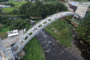
Kano River Crossing Bridge after completing closure
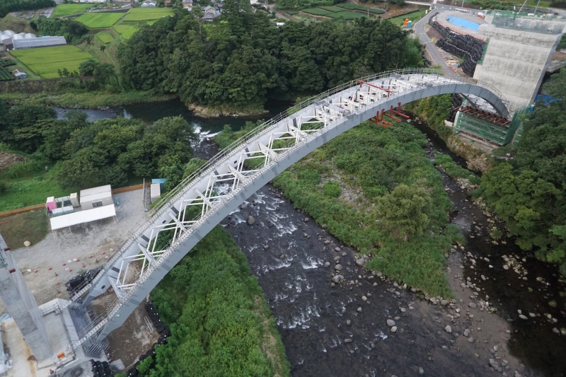
2 General view of the whole bridge
3 Construction procedure
4 Comparison of lowering construction equipment
5 Lowering construction procedure
2
3
4
5
Kano River Crossing Bridge 3 2017
Kano River Crossing Bridge 3 2017 34
thema
center of rotation of the base. By loosening the winch cable in
step 2, the rigid reinforcement is lowered by rotation under its
own weight (photo 8 and 9).
When the angle of the rigid reinforcement is 18° and the
tension is about 600 kN, the winch system is replaced with the
jack system. Photo 10 shows step 3 of the lowering construc-
6 Lowering construction using concrete members
7 Lowering construction using steel members
8 Lowering construction procedure
9 Lowering with the winch
10 3 ton winch
11 Lowering jack system
8 7
6
35
prestressing steel strands with 19 Ø15.2 mm strands were used
for the prestressing tendons to obtain a factor of safety of more
than 2.5 against rupture. Approximately 17 m of prestressing
tendon was launched by the jack system during the lowering
operation. A total of 110 strokes were used for launching, with
150 mm per stroke.
tion; Photo 11 shows the jack system. The jack system is
composed of lowering jacks, prestressing tendons, hydraulic
system and control panel. Two lowering jacks were installed at
the rear of the concrete block set on top of the pier and were
centrally controlled together from a control panel using two
electric pumps. Prestressing tendons tension was at its
maximum at 3040 kN immediately before closure. Two
9
10 11
Kano River Crossing Bridge 3 2017
36
12 Construction procedure of the springing point
13 Rotational bearing installation
14 Rotational test
Rotational bearings with through pin
Figure 12 shows the construction procedure of the springing
point. At first, rotational bearings are installed. Next, steel rigid
reinforcement is erected vertically and lowered by rotation. The
rotational bearing and the steel rigid reinforcement are then
encased in concrete.
Lowering the rigid reinforcement to its position accurately is
important, since the form of the rigid reinforcement after
lowering construction will affect the form of vertical members
and stiffening girders and the form of this arch itself after the
arch rib is completed. The accuracy of the rotational bearing
installation is critical, since it serves as the center of rotation of
the rigid reinforcement. The two bearings at each side were
connected by a pin to reconcile their axis of rotation. Moreover,
the bearings were joined at the plant, transported and erected
together at the site to improve installation accuracy (photo 13).
After completing installation of the rotational bearings, tempo-
rary steel members were installed on the lowering bearings to
perform a test for checking the installation accuracy of the
rotational bearings. Photo 14 shows the confirmation test. By
actually rotating the front while suspended with a crane, it was
confirmed that there were no problems with the installation
positions of the rotational bearings. This measure reduced the
error in the level direction after completing the lowering to
about 20 mm.
Central closure
Central closure was carried out after the rigid reinforcement
members on both sides were rotated and lowered to the speci-
fied height. The central closure spacing was 50 mm. To handle
the gap between bolt hole positions on both sides of the rigid
reinforcement, splice plates were plant fabricated after measur -
ing for the actual hole positions. Immediately after lowering
was completed, the rigid reinforcement on both sides was
connected by temporary splice plates and bolt hole positions
were measured during the night, when temperatures are stable.
Photo 15 shows the central closure; Photo 1 shows the pano-
ramic view after lowering was completed.
Arch rib encasement work
Encasement work for the rigid reinforcement involved encasing
the first block at both ends with concrete from the falsework,
and then assembling the form traveler over the arch rib. Figure
16 shows the structural drawing of the form traveler. The form
traveler weighs 1050 kN. It moves by tensioning a prestressing
steel bar with a 500 kN jack installed in front and propelling
itself forward on the rail installed over the arch rib.
To make the arch rib structure and construction more efficient, a
new cross sectional structure was adopted where the rigid rein
-
forcement is not filled with concrete and is placed outside the web.
12
13
14
thema
Kano River Crossing Bridge 3 2017
37
15 Central closure
16 Construction procedure with the form traveler
17 Structural details of arch ribs
18 Comparison of cross section of arches
19 Conceptual rendering of the bridge
Melan's rigid reinforcement is a temporary steel member, and the
interaction between the steel member and the concrete member is
not considered. The maximum thickness of the member is 25 mm
for flanges and 17 mm for webs, and steel tensile strength is 490
MPa (fig. 17). Figure 18 shows a comparison of the cross section
resulting from the old approach with that resulting from the new
one. By baring the rigid reinforcement inside the box girder, web
thickness could be freely set to its structurally required thickness
and became unnecessary, thereby making construction work
simpler and more efficient. This resulted in lower arch rib weight
and improved seismic resistance.
Conclusion
Lowering construction was employed for the steel rigid rein-
forcement of the Kano River Crossing Bridge. Concrete encase-
ment of the arch ribs is currently underway. Figure 19 shows the
conceptual rendering of the completed bridge. Construction of
this bridge is scheduled for completion in February 2018.
?
?
REFERENCES
1 Makoto, K., Koji, T., (1998). Prestressed Concrete Slant-Legged
Rigid-Frame Bridge Constructed Using the Lowering
Method, Prestressed Concrete in Japan. Prestressed
Concrete Engineering Association, XIII FIP Congress 1998,
Amsterdam, HOLLAND, pp 33-36.
2 Hiroyuki, U., Naoki, N., Mitsuyoshi, N., & Osamu, A. (2015).
Design and Construction for Durability and Maintainability of
Reinforced Concrete Arch Bridge with Curved Girder. IABSE
Conference Nara, Japan.
15
16
17
18
19
maximum thickness
of flange: 25 mm
maximum thickness
of web: 17 mm
concrete strenght: F
c = 40 MPa
melan's rigid enforcement steel
tensile strenght: 490 MPa
Kano River Crossing Bridge 3 2017
Reacties