This paper describes the design and construction of a unique and innovative bridge protection structure: the 'collision protection ramp' that is placed in front of an existing bridge. This innovative concept combines the capacity of a ridged structure with the benefit of minimal ship damage and limited visual impact on the bridge.
108
thema
Bridge collision
protection
ramp Kampen
1
riverbed level is NAP -4,40 m). The bridge and its guiding
structure are not able to withstand the loads of a ship collision
after the dredging works [1].
Consequently Rijkswaterstaat and the city of Kampen decided
to protect the bridge with two collision protection structures
on the upstream (south) side of the bridge and three on the
downstream side. The difference in the numbers is explained
by the fact that ships pass the bridge only through the main
channel when sailing downstream and can pass in two shipping
lanes when sailing upstream.
The contract of the project was awarded to 'Isaladelta', a joint This paper describes the design and construction of a unique
and innovative bridge protection structure: the 'collision
protection ramp' that is placed in front of an existing bridge.
This innovative concept combines the capacity of a ridged
structure with the benefit of minimal ship damage and
limited visual impact on the bridge.
Preface
As part of the project 'Ruimte voor de rivier IJsseldelta' the river IJssel
near the city of Kampen is dredged to a depth of NAP -7,20 m (existing
thema
Bridge collision protection ramp Kampen 3 2017
109
venture of Boskalis and VolkerWessels. The design of the
protection structures was made by Volker InfraDesign and the
construction and installation was done by Van Hattum en
Blankevoort.
Requirements and boundary conditions
The main requirements for the design of the five collision
protection structures were:
- the structures need to protect the bridge from the frontal
impact of a sailing ship of the CEMT Va class at all water
levels between low water (NAP -0,35 m) and high water
(NAP +1,80 m); the energy of a sailing ship on the upstream
side of the bridge is 55 MNm; the energy of a sailing ship on
the downstream side of the bridge is 21,6 MNm;
- the structures need to withstand the side impact of a ship
colliding at an angle of 10° calculated according to the Dutch
design code Richtlijnen Ontwerp Kunstwerken (ROK). The
structures are able to withstand the loads of the above side
impact at all levels between 4 m below low water and 1 m
above high water;
- the structures need to be separated from the bridge, with a
maximum distance of 16 m;
- the structures need to be designed as ramps.
Important boundary conditions for the design and construc- tion were:
- passing ships (safety during construction);
- river discharge (governing for foundation installation and
diving works);
- bridge structure (fig. 2);
- scour protection (had to be removed and replaced).
Construction sequence
After studying the requirements and local boundary condi-
tions, different alternative types of structures and construction
methods were investigated and compared in a Multi-Criteria
Analysis. The structure that was selected is a prefabricated
concrete structure that consists of three parts placed under
water on top of six steel foundation piles that are installed at
NAP -6 m, just above the dredged riverbed (fig. 3 and 4).
Design
One of the most difficult parts of the design of the collision
protection ramps was the calculation of the magnitude of the
horizontal and vertical loads on the structure [2]: a colliding ship
hits the ramp structure (fig. 5) with a high level of kinetic energy
and the front of the ship starts to travel along the surface of the
protection structure (the rear of the ship will sink deeper in the
water). As a consequence a part of the kinetic energy is converted into potential energy and another part is lost as friction (one of
the design requirements was to neglect the energy that is lost by
deformation of the ship hull). During this conversion the forces
on the structure increase and reach a maximum just before the
location where, and the moment when, the ship stops. Figures 6,
7 and 8 illustrate the relation between the forces and the conver
-
sion of the kinetic energy when a ships sails against the ramp.
Important variables in the equations are the angle of the ramp
and the coefficient of friction. These have been varied and the
design is based on 20°. A steeper slope gives higher horizontal
loads (bigger piles) and a more gentle slope gives a longer
concrete structure. For the upstream ramp the energy analysis
results in loads of 12 270 kN vertical and 9140 kN horizontal
caused by the collision. The loads caused by the side impact are
2510 kN perpendicular and 1255 kN parallel. For the loads and
dimensions of the downstream ramps one could say that these
are a factor 3 smaller.
ir. Alex van Schie
Volker InfraDesign bv
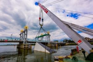
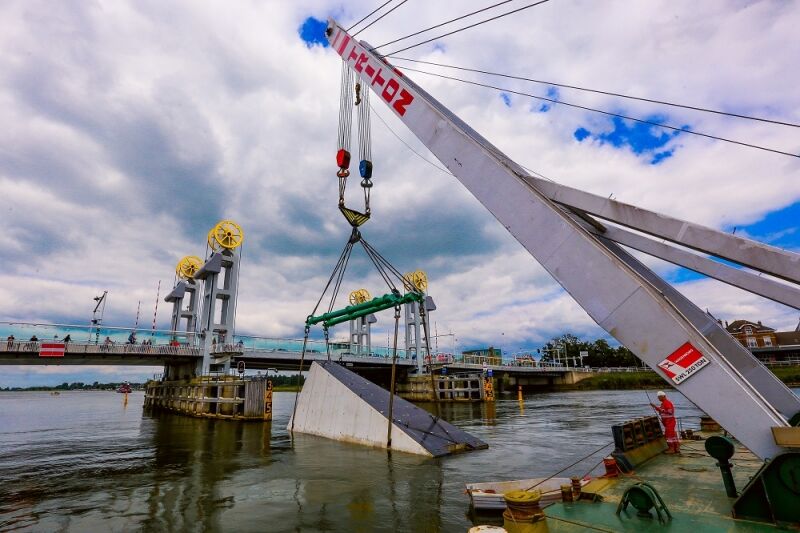
1
City bridge of Kampen, installation of the sections with a sheerlegcredits: Wagenborg2 As built drawing city bridge
3 Collision protection structure
2
3
foundation piles
underwater concrete
1000 mm
sheetpiles
3 cable ducts Ø 219 mm
Bridge collision protection ramp Kampen 3 2017
110
The structural design of the bridge collision protection ramps
[3] resulted in:
- five foundations of six steel piles Ø 1626 mm x 20 mm of
20 m S355J2;
- two upstream protection ramps of (l × w × h)
24,80 × 5,00 × 9,40 m
3 and three downstream - protection
ramps of 19,70 × 5,00 × 7,80 m
3 concrete C30/37;
- a thickness of the bottom sections of 1450 mm (450 mm
prefab + 1000 mm underwater concrete);
- a thickness of the external walls of 600 mm and 500 mm for
the internal walls;
- thirty pile connections with rebar cages of 5900 mm length.
The most critical part of the structural design were the connec-
tions between the three parts and the load transfer to the foun-
dation piles (see chapter 'details'). Also the fact that the lifting
capacity of the sheerleg capable of sailing to the site was limited
to 300 tonnes was a challenge during the design (the middle
part came close to 285 tonnes).
Interfaces
Although deformation of the ship hull is neglected in the
energy equation, it is still present in practice. An analysis of the
ship damage after a frontal collision on the ramp was made by
Marin [4]. Their conclusion is that damage of an unloaded ship
is less than that of a loaded ship and therefore the ramps work
better for unloaded ships. For loaded ship the ramps perform
more like a conventional protection barrier and will damage
the ships hull; the damage is limited to the front 10 m (fig. 9)
and will therefore not affect the cargo.
Details
The fact that all structural connections had to be made under
water (by divers) asked for a set of details that had to be devel-
oped specifically for the project. In particular the two details in
figure 11 took a lot of engineering before they could be finalised.
The lifting points of the bottom section were made of cast in
pad-eyes and the lifting points for the middle and top section
were openings (panama chock) in the walls. The lifting points
have no parts sticking out, to keep the surface of the ramp
smooth. The disconnection of the lifting points could be done
without divers.
The three concrete parts are coupled by tension bars that are
put in vertical ducts in the structure. The bars and bolts fit into
recesses in the roof, to keep the surface smooth. Under the
bottom section bolts are connected and fastened by divers. The
(f ) installation top section
(e) installation middle section (d) pouring underwater concrete (c) lowering of rebar cages into piles
(b) installation of bottom section with rebar cages
(a) installation of steel foundation piles
4
5
waterline
thema
Bridge collision protection ramp Kampen 3 2017
111
20
15
105
0
-5
-10 approaching ship
F
htotaal = 9141 kN F
htotaal = 12 267 kN
F
w
Fn
H
L
-5 05
10 15202530 3540
each other. This casting method also made sure the parts would
fit smoothly on top of each other when placed in the river.
Between December 2015 and May 2016 the fifteen sections
were casted.
fact that the openings in the wall are permanent and all tension
bars can be removed has the advantage that the two top elements
can be lifted of the bottom element after a collision (for repair).
Construction
The thirty foundation piles were installed in November 2015
from a pontoon using both a vibrator and a hydraulic hammer.
The installation tolerances for the piles, that were determined in
collaboration with the contractor were very strict (x, y +/- 50 mm
and z +/- 5 mm). The work sequence and schedule allowed the
contractor to adjust the position of the openings for the rebar
cages in the bottom section to the as built location of the piles.
The concrete sections were casted on a quay in the Zuiderzee-
haven in Kampen, relatively close to the bridge. As all sections
had to be lifted by the floating sheerleg Triton they all had to be
casted close to the waterway. To save room along the quay the
middle and top section of the five ramps were cast on top of
9
+ 0.000 m
N.A.P.
? 7.200 m bottom
1/2 ? ?H
?H
2 / 3L 1 / 3
L
A
d
ship
6
7
60000
50000
40000
30000
20000
10000
00,00 1,15
2,293,44
4,585,736,87 8,029,1610,31 11,45
energy [kNm] and force [kN]
distance [m]
EkinEpotFvshipFwFvtotalFhtotalenergy loss due to friction
4 Construction sequence
5 Relation between the for -
ces and the conversion of
the kinetic energy when a
ship sails against the ramp
6 Forces on Collision
Protection Ramp
7 Parameters in energy
Equation
8 Energy conversion
9 Calculated ship damage
after collision
8
kin pot friction 2 22 2 ship ship shipship
kin
ship ship shipship
2
ship
kin
ship
ship kin
2
ship
2
8 4 sin 2 8 8 sin 2
2
1
sin 2 8
8
2
1
sin 2
EE E
mgHmgfHmgHmgfH
E
d d d d
m gH
f
E d
dE
H f
mg
=+
=+ =+ =
??
=+ ??
??
=
??
+ ??
??
It follows that:
kin pot friction
2 22 2
ship ship shipship
kin
ship ship shipship
2
ship
kin
ship
ship kin
2
ship
2
8 4 sin 2 8 8 sin 2
2
1
sin 2 8
8
2
1
sin 2
EE E
mgHmgfHmgHmgfH
E
d d d d
m gH
f
E
d
dE
H f
mg
=+
=+ =+ =
??
=+ ??
??
=
??
+ ??
??
Bridge collision protection ramp Kampen 3 2017
Bridge collision protection ramp Kampen 3 2017 112
thema
a delay occurred because of the high river currents in July 2016.
Finally all five ramps were placed in August 2016.
After completion of the structures seven steel piles with naviga-
tion signs and lights were placed in front of the bridge collision
protection ramps (photo 10). The lights are powered by solar
panels and battery.
Conclusion
The bridge collision protection ramp is a relatively small struc-
ture with the capacity to transfer very large amounts of ship
energy to a pile foundation without effect on the structure it is
protecting. For the first five structures that are placed in front
of the piers of the city bridge in Kampen all technical challenges
have been overcome. With this experience it is just a matter of
time before other objects in rivers will be protected by ramps
like these.
?
? REFERENCES
1 Zomerbedverlaging Beneden-IJssel Deelrapport 1B Inventa-
risatie Constructies en Kunstwerken. LW-AF20120608/RK
versie 4.0, RoyalHaskoningDHV, 2013.
2 Bergwerf, D. (2015). Addendum Ontwerpbasis Civiel Schan-
scaissons, IJD-SBK-RAP-1004 revisie 2.0.
3 Bergwerf, D. (2015). Berekeningsrapport DO Schanscaissons,
IJD-SBK-RAP-2007 revisie 1.0.
4 Marin (2013), Review van Schanscaissons voor Stadsbrug
Kampen. 27106-001-HSS.
5 Schoffelmeer, M. (2015). Geotechnisch ontwerp DO Schan-
scaissons, IJD-SBK-RAP-2006 revisie 1.0.
6 Schoffelmeer, M. (2015). Beoordeling invloed zomerbedver -
laging op Stadsbrug Kampen, IJD-OIJ-RAP-2005 revisie 1.0.
The installation and connection of the sections was planned in
two phases: first the bottom sections were placed and poured
with underwater concrete and afterwards the middle and top
sections were installed and connected (fig. 1). During the works
HMPE plates (Hakorit)
steel plate
Ø 400 x 50 mm
PVC duct
Ø 200 mm
recess Ø 250 mm
GEWI threadbar
11b
10
10 City bridge Kampen
with the five protec-
tion ramps
credits: Maarten van de
Biezen
11 Details: (a) lifting
point; (b) upper part
of tension rod
11a
r = 100
r = 150
r = 150
r = 150
r = 150
220
600 200
100
100
Reacties