On plot 80 in the Baakenhafen harbour basin in the east of HafenCity Hamburg, Garbe Immobilien-Projekte GmbH is developing the 'Campus Tower'. The construction site of approximately 3800 m2 directly overlooks the Elbe and is located at the mouth of the Baakenhafen and the exit of the HafenCity Universität station of the U4 U-Bahn line. The complex of buildings mainly consists of buildings for office and residential use above a shared two-level underground car park. The gross floor area (GFA) of the planned development is approximately 22 120 m2.
122
thema
Campus Tower in
HafenCity Hamburg
1
The 16-storey tower building with a total height of 56 m and
the adjacent 7-storey office block (ground floor including
gallery level + six upper floors) has been designed by Delugan
Meissl Associated Architects of Austria (fig. 2). The striking
triangular layout of the high-rise has a clear structure and a
clear grid-like glass façade.
In the south-side building, designed by the SOP architect firm
from Düsseldorf, subsidised rental apartments and freehold
apartments will be built directly by the water's edge. Large
windows and continuous south-facing balcony strips create
high-quality living conditions.
On plot 80 in the Baakenhafen harbour basin in the east of HafenCity
Hamburg, Garbe Immobilien-Projekte GmbH is developing the 'Campus
Tower'. The construction site of approximately 3800 m
2 directly overlooks
the Elbe and is located at the mouth of the Baakenhafen and the exit of
the HafenCity Universität station of the U4 U-Bahn line. The complex of
buildings mainly consists of buildings for office and residential use above a
shared two-level underground car park. The gross floor area (GFA) of the
planned development is approximately 22 120 m
2.
Both buildings will meet the highest sustainability standards
and will achieve the Gold standard for the HafenCity environ-
mental certificate. Schüßler-Plan is responsible for the struc-
tural planning (design and execution phases) for the entire
complex of buildings and the design of the construction pit.
Construction pit
The base of the construction pit is 1.44 m above sea level.
Compared to the highest point of the surrounding area, in the
area of the abutment of the Baakenhafen Bridge, the maximum
depth of the construction pit is approximately 8 m. In the area
of lift pits, the excavation base is up to 2 m deeper.
The pit lining walls were constructed as rear anchored bored
pile walls. The piles have a diameter of 750 mm an at a center
to center distance of 1.55 m. The intermediate area is designed
with shotconcrete. The upper 2.50 m of the pit lining will have
to be removed as soon as the construction work is completed.
Therefore in this area a soldier pile retaining wall consisting of
I-beams inserted in the bored piles was realised.
The pit lining walls are planned as 'near rigid supported' foun-
dation pit walls in accordance with EAB (recommendations of
the working group excavation pits). According to the specifica-
thema
Campus Tower in HafenCity Hamburg 3 2017
123
tions of the 'General conditions for licence areas' (Allgemeine
Bedingungen für Gestattungsflächen) of HafenCity Hamburg
GmbH, the horizontal deformations of the pit lining walls are
limited to v
h ? 10 mm [1].
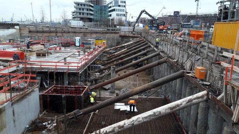
Pit lining on the north side
On the north side of plot 80 a bored pile wall will be realised
for the protection of the Versmannstraße, because a rear-
anchored pit lining is not possible due to the nearby U4 line.
The wall is reinforced with diagonal stays, which are supported
against the partly completed base plate (photo 1). In the
construction phase before the installation of the stays, the
construction pit wall is supported by a berm. As a result, the
required construction processes include interfaces with the
building construction works, which had to be considered in
advance in the planning.
Embankment and quay wall on the south side
Along the south side of the plot, the height difference between
the bottom of the construction pit and the top edge of the
adjacent quay wall (built in 1888) is approximately 3.50 m.
The foundation pit has an incline here of between 45° and
approximately 50°, and the surface is protected against erosion
with shotcrete. This was necessary because the presence of
existing quay makes the application of external anchorage
impossible. Under the shotcrete, there is a drainage layer for
effective water pressure release (fig. 3).
Foundation
In the investigation of underground conditions, in the first 3 m
sandy fillings with soft layers (clay) were found. Next alternat-
ing layers of loosely layered sand and filled soft layers follow.
Only after 8 m densely-packed sand, that is able to take a load,
was found.
As the bottom edge of the structure is largely located in a
filling, the load is transferred to the lower-lying sand that is
able to take a load by a pile foundation. The piles are planned
with diameters of Ø 600 mm and Ø 800 mm, and have a length
of up to 25 m underneath the high-rise. In the calculation of
the floor panel a spring stiffness of 240 MN/m (diameter
600 mm) and 340 MN/m (diameter 800) was applied. In the
case of 9 m pile embedment into the load-bearing sands, a design
load of R
d = 3400 kN was calculated for a 600 mm bored pile.
The vertical loads are diverted with point pressure and surface
friction into the subsoil. Horizontal loads due to wind with
short effect on the buildings and due to the sunk load cases
(one-sided water pressure due to the draining-off of flood
water) are transferred by areas through bedding and bending
of the bored piles. For the horizontal bedding for the piles a
bedding of k
h = 1.25 MN/m 2 was applied in the soft layer.
In addition to the usual load cases, the flood water load case
with a flood level of +7,30 m above sea level and sunk load
cases had to be considered: for the 0.65 m thick base plate this
resulted in a maximum upward pressure of 55.50 kN/m
2. In
total, there are approximately 340 bored piles spread across the
Campus Tower in
HafenCity Hamburg
Markus Krah
Schüßler-Plan Ingenieurgesellschaft mbH 1 View of the pit lining situation on the north side
2 Tower building
credits: Delugan Meissl Associated Architects3 Cross section view of the quay wall and the building pit
2
3 drainage layer for effective
water pressure release
Campus Tower in HafenCity Hamburg 3 2017
124
4
5
4 Overview of the bored
pile foundation
5 Standard layout of the
high-rise
walls 250 mm thick
columns Ø 300 mm
slab thickness 250 mm
thema
Campus Tower in HafenCity Hamburg 3 2017
125
6 3D model in REVIT
entire construction site. Figure 4 shows the distribution of the
bored piles (red: diameter 800 mm; green: diameter 600 mm).
The guideline 'Calculation models for flood protection walls,
flood protection systems and waterfront structures in the area
of the tidal Elbe of the Free and Hanseatic City of Hamburg' [3]
and the 'Guideline for target heights and load assumptions for
the HafenCity district' [4] are also taken into account in the
structural calculations.
The arithmetically estimated pile resistances were reviewed
with a static load test in accordance with 'EA ? Pfähle' [5]
(Recommendations of the Work Group 'Piles'). The load was
applied centrically and axially with hydraulic presses. Steel
trusses were used as abutments for the test load.
Structural design
High rise
The 16-storey tower building and the adjacent office block
extend along Versmannstrasse with a total length of 95 m. The
standard layout of the high-rise has a clear structure with a
support grid on the façade each 5.40 m with a total side length
of L = 32.40 m (fig. 5). The distances to the reinforcing cores is
L = 7.10 m.
The structural design is based on a reinforced concrete with
250 mm-thick flat slabs which are equipped with thermal
component activation in the tower and the office block. The
very slender supports in the high-rise are realised in high-
strength concrete (C 80/95).
The building, which was examined holistically in a three-di-
mensional finite element model, is reinforced through the
stairway cores and lift shafts. In the transition area between the
tower and office building along Versmannstrasse, a 16.20 m
wide passage to the inner courtyard is planned. This will be
realised by a concrete structure in the area of the façade which
will be formed over five floors as a Vierendeel truss (fig. 6).
Residential building
For the residential building, a design has been chosen which
combines the efficiency and variability of the layouts: efficiency
in terms of straight load transfer and flexibility in terms of the
optimal arrangement of walls. In the transfer to the lower level,
the loads were absorbed by roof beams and wall-like supports.
The cantilever balconies in the area of the residential building
are planned as prefabricated components and are fixed with
Schöck Isokorb load-bearing elements in the 220 mm thick
concrete slab.
6
office residential
All plans produced by Schüßler-Plan are shown in a continuous,
spatial 3D model in order to optimise the support structure,
details and planning (fig. 6).
The building is currently being built and should be finished in
spring 2018.
?
?
REFERENCES
1 General conditions for licence areas ( Version
06.05.2015), HafenCity Hamburg GmbH.
2 Geotechnical report, orienting contaminant
investigation: Campus Tower, Hafencity Hamburg,
Plot 80, IGB Ingenieurgesellschaft mbH, 29.07.2014.
3 Calculation models for flood protection walls, flood
protection systems and waterfront structures in the
area of the tidal Elbe of the Free and Hanseatic City of
Hamburg; Free and Hanseatic City of Hamburg,
Department for Roads, Bridges and Waterways.
4 Guideline for target heights and load assumptions for
the HafenCity district; Free and Hanseatic City of
Hamburg, Department for Roads, Bridges and
Waterways.
5 EA ? Pfähle, Recommendations of the Work Group 'Piles',
German Geotechnical Society.
Campus Tower in HafenCity Hamburg 3 2017

Reacties