Where the A12 and A20 motorways merge, before passing under the Gouwe aqueduct, both the flow and safety of road traffic become critical. In order to expand the road network around Gouda, under the name 'A12 Parallel Structure', the province has constructed two new roads: the Extra Gouwe Crossing and the Moordrecht Bow. Within the Extra Gouwe Crossing, the 'Amalia Bridge', designated also as 'ancillary structure KG', showed to be highly challenging; both structurally and in terms of fitting into the existing situation.
18
thema
-0 .6 00 m
- 4 .6 00 N.A .P .
mi
n.7 00 0 2
5 00 0 15
N20 7
3
600 14
13
12
11
10
9
1 2 3 4 5 6 7 8
3 3 660 3 3 985 3 3 985 3 3 985 3 3 994 3 3 255 3 8 642 3 8 29 0 14 362 31 143 30 65 0 30 99 5 30 986 30 622
2
2 50 0
joint
joint
joint
joint
joint
joint
joint joint
joint
joint
joint
joint
joint
joint
CVR building
Amalia Bridge
Waddinxveen
1
New Gouwe bridge beside aqueduct will ease traffic on A12
Where the A12 and A20 motorways merge, before passing under the Gouwe aqueduct, both the flow and
safety of road traffic become critical. In order to expand the road network around Gouda, under the name
'A12 Parallel Structure', the province has constructed two new roads: the Extra Gouwe Crossing and the
Moordrecht Bow. Within the Extra Gouwe Crossing, the 'Amalia Bridge', designated also as 'ancillary
structure KG', showed to be highly challenging; both structurally and in terms of fitting into the existing
situation.
thema
Amalia Bridge Waddinxveen 3 2017
19
1 2 3 4 5 6 7 8 910 11 12 13 14 15
Kanaaldijk
Gouwe
Wilhelminakade
Highway A12
Highway A12 Concorp
Gouwe
N207
- 0 .6 00 m
- 4 .6 00 N.A .P .
mi n.7 00 0 2 5 00 0
15
N207 3600
14 13 12 11 10 9 1 2 34 567 8
33 660 33 985 33 985 33 985 33 994 33 255 3 8 642 3 8 29 0 14 362 3 1 143 3 0 65 0 30 99 5 30 986 3 0 622
2 2 50 0
joint
joint
joint
joint
joint
joint
joint joint
joint
joint
joint
joint
joint
joint
CVR building
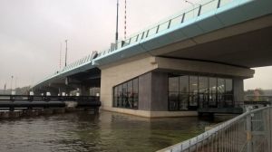
The road crosses the river Gouwe just north of the Gouwe
aqueduct by means of a new drawbridge (photo 1). Apart from
the Gouwe, this structure also crosses local roads (from west to
east): Kanaaldijk (N484), Wilhelminakade and N207. The
bridge consists of a movable section (the leaf, a steel structure),
and concrete approach ramps to the east and west of the bridge
(fig. 2 and 3).
Situation
Because structure KG lies immediately beside the existing
Gouwe aqueduct, this object formed the de facto working
boundary on the south side. With this in mind, and in order to
minimize the impact of construction activity on the existing
aqueduct, it was preferable to place the bridge as far as possible
from the A12 (to the north). It was essential to take into account
not only the visible parts of the Gouwe aqueduct, but also the
subsurface grouted anchors. However, another barrier was
formed by several commercial properties on the northern side.
One of these properties is a confectionery manufacturer
(Concorp), whose production depends on sensitive weighing
equipment. Together with the aqueduct, these factors
constrained the position of the bridge in the north-south direc-
tion. Likewise, the position of the western abutment was
restricted by the presence of another existing object: a road-
traffic control centre. This building is equipped with ICT
equipment for control of traffic systems, and therefore has a
critical function in traffic management. To avoid jeopardizing
this building and its function, the western bridge abutment has
been positioned at a sufficient distance. Fortunately, the location
of the eastern abutment was not subjected to any positional
constraints. What did determine the position was the maximum
extent for the approach embankment in order to maintain the
necessary landscape quality in the vicinity of the structure.
Design of deck structure
The total length of structure KG from eastern to western
abutment is approximately 450 m. The bridge is divided into an eastern approach ramp (124 m), the bascule pit and steel leaf
(together 45.5 m) and the western approach ramp (280 m, all
lengths approximate). The required 2 × 2 lanes, in combination
with a median of about 3 m width (ensuing from the landscape
plan), and bevelled fibre reinforced plastic edge elements
(ensuing from the visual quality plan) result in a total deck
structure width of approximately 21.6 m (fig. 4).
Construction method
To construct the approach ramps quickly and with minimal
disruption to the surroundings, the deck structure was built
using precast concrete beams. The first beams were placed in
position from the side of the abutments, while the remaining
sections were hoisted into position by cranes from each finished
section of the deck. This working method meant that there were
almost no interruptions to traffic on the underlying road
network. Moreover, this also avoided the need for temporary
structures to create a stable foundation for the cranes on the soft
Gouda ground. Nevertheless, this did make it necessary to
dimension both the deck and its substructure for the crane load.
ir. Bas van den Berk
Heijmans Infra
1
Amalia Bridge over the Gouwe, Waddinxveen
2 Top view on the Amalia Bridge
3 Longitudinal cross-section
2
3
Amalia Bridge Waddinxveen 3 2017
20
20 980
40002660
6599
19 920
14 500 2660
4000
2000
81.160°
93.550°
N.A.P.
4 Cross section
5 The land piers are designed as double T-pillars on a footing which is founded
on precast concrete piles
6 T-heads that hold the rods to the ends of the deck supporting beams
This enabled the construction of a foundation structure that fits
into the existing situation (grouted anchors of the Gouwe aque-
duct) but is still wide enough to support the deck structure. The
land piers are made of concrete with strength class C55/67.
To achieve sufficient load-bearing capacity in the soft Gouda
subsoils, it was necessary to drive the precast concrete piles
approximately 10 m into the firm sand layer. This resulted in a
pile toe depth of 20 to 25 m below sea level. Piling and vibration
analyses carried out beforehand indicated that pile-driving was
feasible, and would not lead to unacceptable risks for existing
objects, particularly the traffic control building and Concorp.
The subsequent pile-driving work proceeded smoothly, and all
piles were placed at the correct depth in the correct manner.
A challenge for the pier design was the fact that the outer box
girders, each up to 38 m in length, had to be placed on a 4 m
long cantilever on top of the pillars. As described earlier, it was
also necessary to consider crane loads together with the hoist-
ing weight of the precast beams. As a consequence, the upper
reinforcement in the deck support beams incorporates several
layers of Ø40 mm rods. These rods are mechanically anchored
to the ends of the deck supporting beams by means of 'T-heads'
(photo 6) in order to avoid complicated reinforcement detailing
in that small space at the end of the construction.
River pier
Row 11 is the position of the support pier for the moving leaf
of the drawbridge. This pier stands in the river Gouwe. The
geometric and structural design of this pier is similar to that of
the land piers. There is one major difference: this river pier has
to be able to withstand a collision from water-borne traffic. As a
result of the magnitude of this load, prefab concrete piles could
not be used, so steel tubular piles were used for this foundation.
To optimize the tubular pile dimensions, a more detailed analysis
of the navigation channel and nautical traffic was carried out
resulting in a reduction of the collision loads, which meant that
Structure
The span dimensions are based on several preconditions. First
of all, the beams could not be too heavy, due to the chosen
construction method. Furthermore, the positional constraints
arising from the current situation (i.e. traffic control building,
Kanaaldijk, the necessary distance from the Concorp site,
Wilhelminakade, intersection with the Gouwe and the N207)
also played a significant role. Finally, it was desirable to choose
a beam length that could be repeated as often as possible. For
the eastern approach ramp this resulted in four spans of 31 m,
and for the western approach ramp, six spans of 34 m and two
spans of 38 m (approximate lengths). The transition from span
to span is formed by non-rigid expansion joints and rubber
expansion joints in a steel claw. The spans are constructed from
precast concrete I-beams with tapered box girders at the sides.
Land piers
At rows 2 to 8 and 12 to 14 (fig. 2 and 3), the deck structure
rests on land piers. These piers are designed as double T-pillars
on a footing which is founded on precast concrete piles (photo 5).
4 5
6
thema
Amalia Bridge Waddinxveen 3 2017
21
7 An analysis of the navigation
channel and nautical traffic
led to a reduction of the
collision loads and smaller
tubular pile dimensions
8 Bascule pit: the beam at
row 9 is modelled schema-
tically as a rib that is part of
the 2D element, which itself
is the roof of the bascule pit Obviously this had to wait until the steel leaf and ballast box were
in place. Because the beam was still not finished at that point in
time, and, therefore it lacked sufficient strength to support the
prefabricated deck beams, a temporary support structure was
built below the beam, which was later removed once the roof was
ready. The same SCIA Engineer model was used for this phase as
for the final phase, except without the roof. In addition to the
models for the purpose of the overall structural analysis, a separate
model was also made to determine the forces in the consoles.
These consoles are cantilevered from the concrete wall, and are
subject to dynamic forces from the moving parts. A push-pull rod
transfers forces from the leaf to these consoles via the panama
wheels: large pinion-driven gears that open and close the steel leaf
of the drawbridge. A complicating factor in the structural analysis
is the varying angles at which the forces act on the concrete
consoles, depending on the position of the steel leaf. Another is
the fact that the forces also switch from tensile (when the bridge
is raised) to compressive (when the bridge is lowered).
On December 23 2016, the bridge was opened , providing the
alternative route for traffic. As a result, one can choose such a
route so that the traffic jam is avoided and with this, the problem
of major bottleneck is solved. Although it was a challenge to fit
the Amalia Bridge in the existing situation, Heijmans has
managed to engineer and successfully build the bridge on
time.
?
?
PROJECT DETAILS
project Bridge over the Gouwe river (part of A12 Parallel Structure)
client Province of South-Holland
contractor Heijmans Infra
architect Zwarts and Jansma
structural design Heijmans Infra
first pile bridge KG 12 June 2015
bridge KG opening end of 2016
smaller tubular pile dimensions would be sufficiently robust
(photo 7).
Final phase of bascule pit modelling
The bascule pit (photo 8) was structurally analysed using a 3D
schematic model in SCIA Engineer. In this model, the beam at
row 9 is modelled schematically as a rib that is part of the 2D
element, which itself is the roof of the bascule pit. This beam
spans approximately 15 m, and bears the weight of the precast
deck above. Because the forces acting in this beam are dependent
on the stiffness of the corner columns that support it, the analysis
was performed both with the cracked and uncracked columns.
Construction phase
The preceding paragraph concerns the final phase. However,
the roof was not yet in position during the construction phase.
7
8
Amalia Bridge Waddinxveen 3 2017
Reacties