The light rail connection between Rotterdam and The Hague was using the heavy rail tracks of the Dutch Railway company as a temporary solution. However, in the final situation, a separate platform was required. This paper describes the design and execution of this new platform which was complicated due to the restricted size of the building site and tight time schedule.
80
thema
From architectural
vision to reality
1
Designing and Building the new E-line station Den Haag
The light rail connection between Rotterdam and The Hague was using the heavy rail tracks of
the Dutch Railway company as a temporary solution. However, in the final situation, a separate
platform was required. This paper describes the design and execution of this new platform which
was complicated due to the restricted size of the building site and tight time schedule.
thema
From architectural vision to reality 3 2017
81
x=82106829
.4086
y=455228631
.4710
x=8216484 2
.5934
y=455355760
.2954
peil = 110
de bestaand e situa
luik
busplatfor m conform bestaande indeling
kolom
v.v. hw a + k&l
kolo m
v.v. hw a + k&l bk midde n perron14000+NA Pbk spoo r13700+NA P roltrap (30°)
oot
hwa-goot oo
t hel lingbanen 1:13,6
h=25 0,
l=3400m m hellingbaan 1:16
h= 300,
l=4800mmhellingbaan 1:16
h= 300,
l=4800m m hellingbanen 1:13,6
h= 250,
l=3400mmhellingbanen 1:13,6
h=25 0,
l=3400mmhellingbanen 1:13,6
h=25 0,
l=3400mm
hel lingbanen 1:13,6
h=25 0,
l=3400m m hellingbaan 1:16
h= 300,
l=4800mm hellingbanen 1:13,6
h= 250,
l=3400mmhellingbanen 1:13,6
h=25 0,
l=3400mmhellingbanen 1:13,6
h=25 0,
l=3400mm bk midden perro n14000+NA Pbk hoog perron14700+NA P
bk hoog perron14700+NA P bk spoo r13700+NA P
bk spoo r13700+NA P
bk vluchtpa d14000+NA P
bk vluchtpa d14000+NA P bk spoo r13700+NA Pbk spoo r13700+NA P hellingbaan 1:12h=233mm, l=2800mmhellingbaan 1:12h=233m m, l=2800m mhellingbaan 1:12h=233mm, l=2800m m hwa-goot aardenbaa n met ballastbedaardenbaa n met ballastbed zettingsvrije plaa t met ballastbedballastloo s spoor geluidscherm tussen sporen0,60+NA P 8,00+NAP
8,00+NAP4,30+NAP
3,95+NAP
0,80+NAP1,70+NAP
H-1
H-2
H-3
H- 4
H-5
H-7 H-8 H- 9 H-10 H-11 H-6 39000 2192 0 27400 27400 36000 27400 36000 36000 36000 36000 27400
HL-2 10960HL-1
x=82106829
.4086
y=455228631
.4710
x=8216484 2
.5934
y=455355760
.2954 H-2
H- 3 H-4 H-5 H-7
H- 8
H-9 H-1 0
H-11 H- 6 3900 0 21920 27400 27400 36000 27400 36000 36000 36000 36000 27400 HL-21096 0HL-1 H-1
H-A
Anna van Buerenplei n
Anna van Buerenstraa t
La Fenetre Nationaal Archief
Laurens
Reaels
traat
Hendrick
Hamelstraa t
Jan
Centraal Station Busplatform Centraal Station Centraal Station spoorwegemplacement
Lekstraat Rijnstraat
Schenkweg
Schenkviadu ct
Prins
Be rnhardv ia d uct
HS E
fietsenstallin g
ontwerp spoorpar k
(nie t in scope)
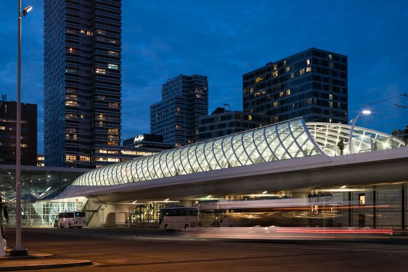
On August 22nd 2016, approximately 2 years and 4 months
after the project was awarded to BAM Infra, the 'Haags Start-
station E-lijn' (photo 1) was opened to the public.
Prior to the contracting phase the stake holders, such as the
City of The Hague, public transport companies of The Hague
(HTM) and Rotterdam (RET), ProRail and various advisors,
such as ZJA Zwarts & Jansma Architects and Movares consultants
& engineers studied various options and conceived an architec-
tural solution that fitted into the masterplan for The Hague
New Central. In the proposed solution emphasis was given to
transparency and slender curved shapes. This architectural
design was the basis for the public procurement of the project.
(photo 2).
In the phase prior to contracting it was determined that the
station should be located on level 2, above the existing train
station (level 0) and the bus station (level 1). This decision was
driven by the lack of space for a new light rail station in
between the existing station, bus platform, underground
parking in the Anna van Buerenstraat and other existing
structures (fig. 3).
At the location of the station a 323 m long viaduct
through the Anna van Buerenstraat passing over the Prins
Bernhardviaduct into the Laurens Reaelstraat was required.
The passage over the Prins Bernhardviaduct with a 4.70 m
clearance determines the level of the station. After this passage
the rails lower to ground level with a 3,75% slope. Figure 4
gives an overview of the project. The first part of structure
consists of ground works, an U-shaped concrete structure filled
with sand on deep foundations and an abutment. The second
part consists of a steel deck supported on 10 steel columns
supported by concrete bases on deep foundations. The last
column is attached to a services building where passengers can
access the bus platform or the train terminal. The last part of
the steel deck is wider and is provided with a roofing of steel
beams and glass. In this part of the deck is the platform where
passenger can enter and leave the light rail wagons. The reference design of the Client contemplated a viaduct with
10 separate steel spans varying from 22 m to 36 m placed on
top of steel columns. Especially in the narrow Anna van Bueren-
straat various problems had to be overcome. First of all this
street had to stay open to traffic during construction because of
the exit from the underground parking. Passenger streams
towards and from the station had to be allowed and also access
for the emergency services had to be ensured. However, a
major part of the structure would have to be assembled over
this street (fig. 3). Additionally both the bus station floor (rail
station roofing) on one side and the underground parking on
the other side had limited weight carrying properties which
limited heavy lifting possibilities around the Anna van Bueren-
straat.
In cooperation with co maker Iemants Steel Structure, BAM
Infra opted for an important design change during the tender
phase. It was decided to convert the 10 single span Client's
design into a continuous bridge deck of 323 m which had to be
shoved into its final position and would be prefabricated on the
other side of the Prins Bernhardviaduct.
From architectural
vision to reality
Jorrit Blom
BAM Infraconsult 1
Haags Startstation E-lijn
2 Artist's impression
3 Situation
bus platform
Den Haag CS
Prins Bernhardviaduct
underground parking
heavy rail tracks ProRail
3
2
From architectural vision to reality 3 2017
82
BUS PLATFORM deck part A
deck part B
deck part C
deck part C
deck part B
4 Longitudinal section of the project
5 Sequence of deck sections
6 Lifting jacks on right and left side, moving jack in the middle
7 Shoving deck part A over auxiliary structures (blue)
8 Position of bearings in Client's reference design.
deck sections were shoved towards their final position. The rest
of the sections were assembled directly on their final position.
In figure 5 the process is schematically pictured. First deck
part A was assembled on a prefabrication platform. After part
A was finished and shoved to its final position, part B was
prefabricated on the same platform. After part B was shoved
into its final position deck parts C were assembled directly on
their final position.
During the process of shoving, the deck was supported alter -
nately by lifting jacks and moving jacks (fig. 6). The jacks were
placed on top of an auxiliary structure around each column
(fig. 7). When the deck was supported by the jack in the middle
the horizontal jacks on each column made a stroke from left to
right. When the stroke was finished the jacks on the left and
right lift the deck and the jack in the middle was moved back
from right to left where the deck was released back on to the
moving jack. This way the deck part was moved approximately
2 m during each stroke. During one weekend deck part A was
moved over 100 m.
By changing the designed building method some new engi-
neering challenges had to be solved. The continuous span led
moving jack
horizontal jack
lifting jacks
Through this change the safety could be improved significantly and
hindrance during the execution could be reduced. The biggest part
of the construction activities for the steel deck were moved towards
the Laurens Reaelstraat with more space, less passengers and better
options for heavy lifting of bridge deck elements. Only the first two
4
5
6
plate with pile foudation abutment
ground works fixed point
323 m 80 m
150 m
thema
From architectural vision to reality 3 2017
83
200 010 2 00x6 01 00x6 0
1,315+NAP
NAP
7,465+NAP
14,70+NAP
14,00+NAP
20,65+NAP
14,00+NAP
1,045+NAP
Anna van Buerenstraat
bearings
treinstation
busplatform
treinstatio
n 1,08+NAP = 0,20-peil NAP
12,30+NAP o.k. spoorligge r
PrinsBernhardviaduct busplatform
treinstation
HSE-hal
hwa-g oot
inspectie-luik inspectie-luik inspectie-luik inspectie-luik insp ectie -luik inspectie -luik inspectie-luik inspectie-luik inspectie-luik inspectie-luik ins
pect
ie
-lu
ik i
n spe
cti
e -lui
k inspectie-luik inspectie-luik 3.4 Personeelsruimte RE T 3.1 3.2 3.5
techniekruimte 1.1
vloerpei l gelijk aan lift voor kabe l invoeris mogelijk indien gewenst.
techniekruimte 2.1
techniekruimte 0.1
inspectie-luik
hwa-g oot
0.1 Liftschach t
7600+Pbk vloer HSE
14355+ Pbk luifel
NAP=PEIL1045+Pbk vloer OVT
7465+Pbk vloe r OVT
14000+ Pok plafon d luifel 12300+Pok ligger HSE
20600+ Pbk. constructi e kap
11410+Pbk vloer/bordes10800+Pok plafond RE T
18600+ Pbk lift
14700+Pbk perron
7465+Pbk vloer OVT
1100+Pbk vloe r HSE
7600+Pbk vloer HSE
4350+Pbk vloer HSE
1045+Pbk vloer OVT
3900 0 21920 27400 27400 27400 H-6 H-5 H-4 H-3 H-2 H-1 2740 0 HL-2 10989 HL-1
licht-/cameramas t licht-/cameramast licht-/cameramast licht-/cameramas t licht-/cameramast licht-/cameramast licht-/cameramast
with small foundations were not capable of absorbing the
summed forces from the friction and breaking forces of the
metro. Also the Client did not wish an expansion joint in the
railway track. Therefore the fixed point was chosen at the
abutment. This choice resulted in ULS-movements of the
bridge of approximately 350 mm on the other end where the
platforms are located.
to bigger displacement due to temperature. Also the continu-
ous girder in combination with the slender architectural
columns called for special measures to assure stability of the
deck. In the Client's reference design the separated decks where
supported by a fork shaped beam on top of the columns (fig. 8).
In order to shove in the deck, the support width of the deck
had to be drastically reduced. Apart from these challenges
induced by the design change it was necessary to integrate
different parts of the design from different subcontractors into
one integrated design solution.
Displacements
The slender bridge deck is supported by slender columns with
a maximum diameter of 2 m. The top level of the rail track in
the station is approximately 13 m above ground level. At the
start of the viaduct an abutment is projected and on the other
end a services building with elevator shaft and automatic stairs
are located.
The bridge deck had to have a longitudinally fixed point.
Because of elongation due to temperature the other supports
had to be provided with sliding bearings. The slender columns
auxiliary support
structures
deck part A
7
8b
8a
viaduct viaduct platforms
services building
transfer to level 0 and 1 services building
transfer to level 0 and 1
323 m
bearings
From architectural vision to reality 3 2017
84
9 Movements of roofing and bridge deck
10 Roofing structure (a) and mock up connection grid beams after testing (b)
In figure 9 it is illustrated how the bridge deck slides over the
supports on top of the slender columns and how the architec-
tural roofing fixed to the services building (red) is sliding over
the bridge deck (green). Therefore, with increasing or decreasing
temperature the bridge deck and the roofing move in opposite
directions.
The glass roofing is supported by sliding bearings placed on
top of the bridge deck. The roof structure consists of an edge
beam and grid beams. The complete structure is hot dipped
galvanized. All bolted connections are made on site. The esti-
mated stiffness of this connection was verified by building and
testing a mock-up of this connection (photo 10b).
Integration
Aside the challenges that resulted from the design change, the
architectural requirements imposed another challenge. The
architect made an 'open' design using slender curved shapes.
The Client had opted for a design that should be a landmark
and it was contractually arranged that all designs and design
stages had to be approved by the architect ZJA. The architect
was to make sure that the artistic impressions made at the start
would be transformed into reality.
From the beginning it was clear that due to the complex three
dimensional shapes and the great variety of disciplines a Build-
ing Information Model was needed. The model started with the
3D-Design of the architect ZJA and a point cloud of the existing
situation. Each design step was checked against this model.
Each company worked in its own software application. The
different designs were checked with the original visualization
and the interfaces between the different designs were adjusted.
grid beams
edge beam
10b
10a
9
thema
From architectural vision to reality 3 2017
85
11, 12, 13 From design to Building Information Model to reality
Emphasize was given to sharing models as early as possible to
get an early insight in possible clashes and the use of limited
space. Also, it was a contractual requirement to keep cables,
piping and bolted connections out of sight. This resulted for
example in a detail in which the bolted connections of the grid
beams of the roofing were hidden behind speakers and light
spots.
This approach made it possible to stay close to the original
visualization (fig. 11, 12 and photo 13), get timely design
approvals from the architect and effectively integrate different
designs. Also the model was used to gain insight into difficult
details preparing the execution of the works.
Conclusions
The design change that shifted the construction works from the
crowded Anna van Buerenstraat to the more spacious Laurens
Reaelstraat was crucial for BAM Infra to get the contract.
The use of BIM-technology and the tight cooperation between
client, contractors, co-makers and subcontractors were key
factors to complete the project successfully and realize the
landmark as desired by the client.
?
11
12
13
bus platform
Anna van Buerenstraat HSE
From architectural vision to reality 3 2017

Reacties