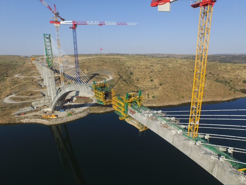
The high speed railway line Madrid-Lisbon crosses over River Almonte with a great 384 meters arch made of high performance self-compacting concrete (C80). The construction of the viaduct, with a total length of 996 m, started in April 2011, and its loading tests were undertaken late 2016.
113
thema
Almonte
River Viaduct
1
High performance self-compacting concrete arch bridge
for HSR-line Madrid ? Lisbon
The exceptional span of the arch and the specific considera-
tions of high speed rail (HSR) bridges (dynamic effects by
passing trains significantly larger than road traffic, significant
horizontal loads and fatigue) led to the design of an innovative
structural scheme in HSR arch viaducts, using two separate
hexagonal sections in the arch springing that join into an
octagonal one in the central stretch of the arch (fig. 2).
In order to verify the structural behavior for static and dynamic
loads (deflections, accelerations), specific verifications and
advanced nonlinear structural models, for every stage of the
construction, were carried out. The stability of the arch was
verified for all the critical loading combinations, making a
geometric-and-material nonlinear analysis, and using step-by-
step iterative techniques.
The complex erection procedure required unique and specific
auxiliary members during construction. The arch was erected by
the cantilever construction method with the aid of temporary The high speed railway line Madrid-Lisbon crosses over River
Almonte with a great 384 meters arch made of high performance
self-compacting concrete (C80). The construction of the viaduct,
with a total length of 996 m, started in April 2011, and its loading
tests were undertaken late 2016.
During the initial stages of the project, different structural
alternatives for the Almonte River Viaduct were analyzed in a
detailed typological study, considering simultaneously its final
behavior as well as its erection procedure. Some of these alter -
natives included cable-stayed, frame type and variable depth
truss deck options. The multi-criteria analysis highlighted the
concrete arch solution as the most economical, the best in
terms of durability and maintenance conditions, and the one
that guaranteed a better structural behavior against dynamic
trainloads and wind.
Guillermo Capellán,
Javier Martínez,
Emilio Merino
Arenas & Asociados,
Ingeniería de Diseño
Pascual García-Arias
Idom
1
Viaduct over River
Almonte in Spain
almost finished
Almonte River Viaduct 3 2017
114
cable-stays from two temporary steel towers, using form travelers
specially designed for this bridge; while the deck was constructed
using an overhead movable scaffolding system (commonly used
method in Spain for HSR concrete box-girder viaducts).
A detailed analysis of all construction phases was performed
together by designers (DJV Arenas&Asociados-IDOM) and
contractor's technical services (CJV FCC-Conduril) during the
construction-stage, and a complete monitoring program was
developed to control every step of the building process.
Construction procedure
The construction procedure was developed such that the
impact and hinder on the Reservoir of Alcántara is minimized.
The main arch crosses over it at a height of almost 60 m, with
two access viaducts at both ends completing this scheme. These
access viaducts, with moderate typical spans of 45 m, have the
same deck geometry over the arch (fig. 3b), in order to use the
same overslung movable scaffolding system.
The arch is erected with a cable-stayed cantilever method
(photo 4). The total length of the arch is divided into 33 cast
in-situ segments on each half, with an approximate length of
6.70 m, plus the key central segment. A cantilever formwork traveler that fits to all geometries of the arch allows its concret-
ing segment to segment.
In order to ensure that stresses are lower than allowable and the
optimal geometry is maintained, the segments are supported by
stayed cables during the construction.
There are 26 pairs of stay cables on each side with their corre-
sponding back stays. Cables 1 to 8 (shown in yellow on fig. 5)
are anchored to the piers rising on both riverbanks.
The anchorages for cables 9 to 26 (blue on fig. 5) are set on the
temporary steel pylons built over piers P6 and P15. Cable forces
are adjusted during the construction whilst some cables at
intermediate construction stages are being released for avoid-
ing excessive stresses.
After the arch closure is reached, cranes and temporary towers
are dismantled to continue with the spandrel columns erection.
Subsequently, the last 42 m deck spans over the arch are
concreted with the same standard movable scaffolding system
(fig. 6 and photo 1).
Other special construction features also deserve to be mentioned:
-
Arch's foundations:
The arch abutments are two reinforced concrete blocks of 7400
and 6300 m
3 that spread the compression loads to the bed rock.
The rock around the blocks is heavily injected with 255 tons of
cement in order to fill all cracks and discontinuities.
- Retaining foundations:
The global equilibrium of the 192 m half-arch cantilevered
structure is achieved with multiple anchors placed at the
retaining foundations adjacent to the riverbank piers. These
anchors have a length of between 22 and 26 m, with a
prestressing load of 2000 kN.
2
3a 3b
2 Conceptual sketch of the designed bridge
3 Arch (a) and deck (b), typical cross section
4 Cantilever construction of the arch
14.00
6.00
1.60
1.16
1.16 1.16 1.23
1.211.231.64
3.30
0.75 0.75 7.00
max 3.00 2.76
2.96 0.20
3.10 1.10
1.44 1.63
0.82
drainage axle
track axle
protection bars against birds
collision axledouble
track axle
catenary posts 7.00
4.80
0.42
0.42
2.20
2.20
6.00
"Z" grade line
arch-deck linkfix point
moderate distance between
piers and spandrel columns
cast-in-situ movable
scaffolding system
conventional
bearings
rock close
to the soil
surface splitting of the arch
into two legs
transversal
stiffness / stability octagonal cross-section
for arch, piers and
spandrel columns
aerodynamic behaviour
thema
Almonte River Viaduct 3 2017
115
5 Numbered scheme of the arch segments and temporary stay cables
6 Last construction stages of the deck
7, 8 Cantilever formwork traveler
enough corrosion protection is achieved by a semi-bonded
individual HDPE sheath extruded into the strand after the
interstices were filled with wax.
Usually both ends of the stay cable were articulated in vertical
direction in order to facilitate their installation.
-
Cantilever formwork traveler :
The concreting of the arch is made segment by segment with
a cantilever formwork traveler (photo 7 and 8) that fits to all
geometries of arch: from segment 1 to 15 the arch is two
legged and from 16 to 33 is only one piece varying in width
and depth.
- Temporary towers :
The articulated temporary steel towers were placed on the
arch's edge piers. A rotation operation was
undertaken in order to raise both towers from their horizontal
position over the deck (fig. 9 and photo 10). This procedure
was composed of four different
erection stages:
1. hinge placement;
2. tower assembly and auxiliary members' installation;
3. rotating operation;
4. disassembly of auxiliary members. This system allowed
execution time savings.
- Temporary stay cables :
The stay cables are individually-protected multi-strand
cables, identical to permanent stay cables (steel type Y 1860
S7; 150 mm
2 section). The number of strands varies from
?15 to 53 (15.2 mm each). The strands are not galvanized as
4
5
6
Almonte River Viaduct 3 2017
Almonte River Viaduct 3 2017 116
thema
Table 1 Recorded parameters of Almonte Bridge (only one semi-arch)
N° parameter points of recording
1 wind direction 1
2 wind speed 1
3 external air temperature 1
4 internal arch air temperature 1
5 stay cable temperature 6
6 concrete arch temperature 12
7 concrete pylon temperature 4
8 steel tower temperature 4
9 foundation clinometer 4
10 concrete pylon clinometer 1
11 steel tower clinometer 2
12 arch clinometer 2
13 concrete pylon clinometer 1
14 arch rebar strain gauge 12
15 steel tower strain gauge 4
16 stay cable strain gauge 40
Monitoring of the bridge
The erection of a bridge with such particular construction
features requires permanent structural monitoring, starting
during its execution and continuing throughout its entire
service life. For a perfectly controlled and functioning structure,
it is essential to know the behaviour of the different sections,
which will enable monitoring of its service life conditions. For
this reason a full scale measurement program was implemented.
Staff was organized at three levels that influence each other and
interact continuously:
1. A surveyor company records, maintains and presents the
data showing the behavior of the structure.
2. A primary analysis makes an immediate coherence evalua-
tion with theoretical predictions providing them to the
bridge designer, and simultaneously assesses the perfection
of records.
3. At this level, the total station survey is compiled with an
automatic data-acquisition measurement system.
4. This primary analysis is developed by an independent
engineer, different to the staff of levels one to three.
5. A secondary analysis evaluates in depth the correlation
with theoretical predictions and makes corrections to
model calculations in order to improve the accuracy of
forecast and appraise the origin and consequences of
divergences. The installed system initially included
93 points of recording in each side of the bridge, listed
in table 1.
7
8
117
9, 10 Elevation of temporary steel tower
11 Geometry control points of cantilever
formwork traveler
cantilever arch at any stage and compare it with theoretical
calculations. This way the structure could be controlled along
its whole length and at any time during erection.
Since movements of the different stages grew and the system
became more flexible, and therefore more susceptible to other
effects (e.g. temperature on the stay cables), alarms were
defined in sections of segments. The allowed tolerances were:
segments 1 to 15 (±50 mm), segments 16 to 13 (±100 mm) and
segments 24 to 32 (±180 mm).
It should be noted that the final construction errors were never
greater than 88 mm.
Conclusions
The use of vanguard current technology and construction tech-
niques, has allowed the execution of this engineering challenge.
Among them all, it must be highlighted the high performance
concrete allowing to adopt a more slender arch section, the
four legged arch configuration, the nonlinear and evolving
calculation software and techniques, the aeroelastic wind
tunnel modelling, and the semi-probabilistic normative treat-
ments, as key elements for the design and structural validation
of the Viaduct over River Almonte.
?
The system was further improved with the addition of 5 accelero-
meters on the arch to analyze the dynamic behavior with the
following purposes:
1. Continuous measurement and recording of the vertical and
horizontal accelerations;
2. Empirical evaluation of vibration modes of arch in construction
stages;
3. Evolution of vibration modes of the bridge in time.
Data was automatically transformed to the engineering units
on site, and presented via website to the three supervision
levels.
Geometry control of arch construction
For an optimal structural performance, the arch's geometry
should match the best as possible with the geometric thrust line
axis for all load combinations. It is concluded that the best
practice and construction philosophy, is to achieve structure's
overall geometric control, by performing field survey work and
erection operations (forces of stays and cantilever formwork
placement) to a meticulous degree of accuracy.
In this sense, it was necessary to carry out continuous and
comprehensive studies of the structure under each erection
stage, determining the corresponding stress and geometric
data, preparing a step-by-step erection procedure plan and
incorporating any checked measurement that was desirable.
Under certain construction load conditions (wind, temperature,
gravity loads), it was necessary to check the structural integrity
of arch, stays, piers and foundations.
The placement of cantilever formwork travelers was controlled
by four reflectors fixed at the end of the formwork (fig. 11). It
was then possible to determine the position of the end of the
10
11
9
reflectors on
left formwork
reflectors on
right formwork
direction of arch
construction
elevation of cantilever formwork Di
view "A" Bi
Cd
Dd
Bd
Ai
"A"
TH Ci
Ad
A/C
B/D
H
0.75
Almonte River Viaduct 3 2017

Reacties